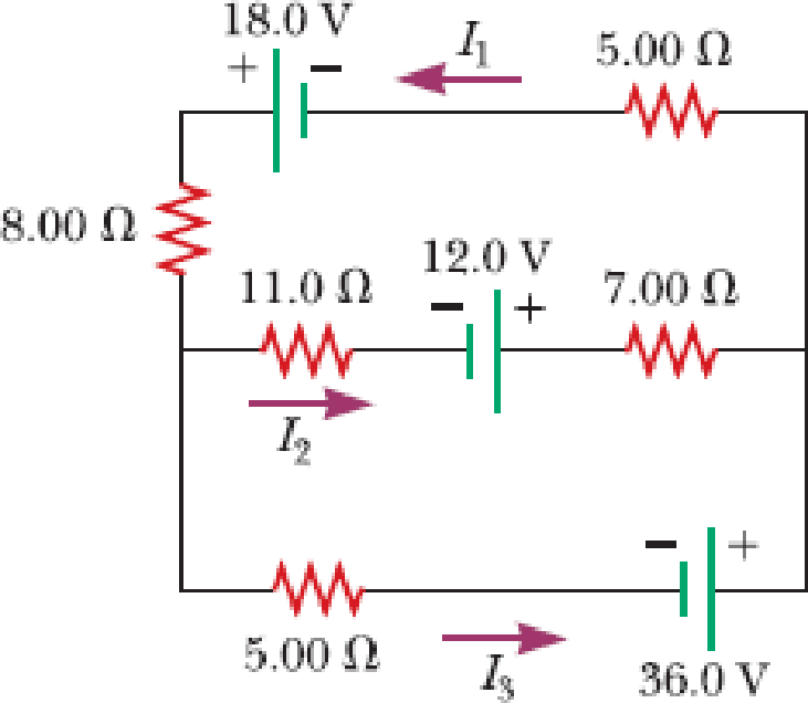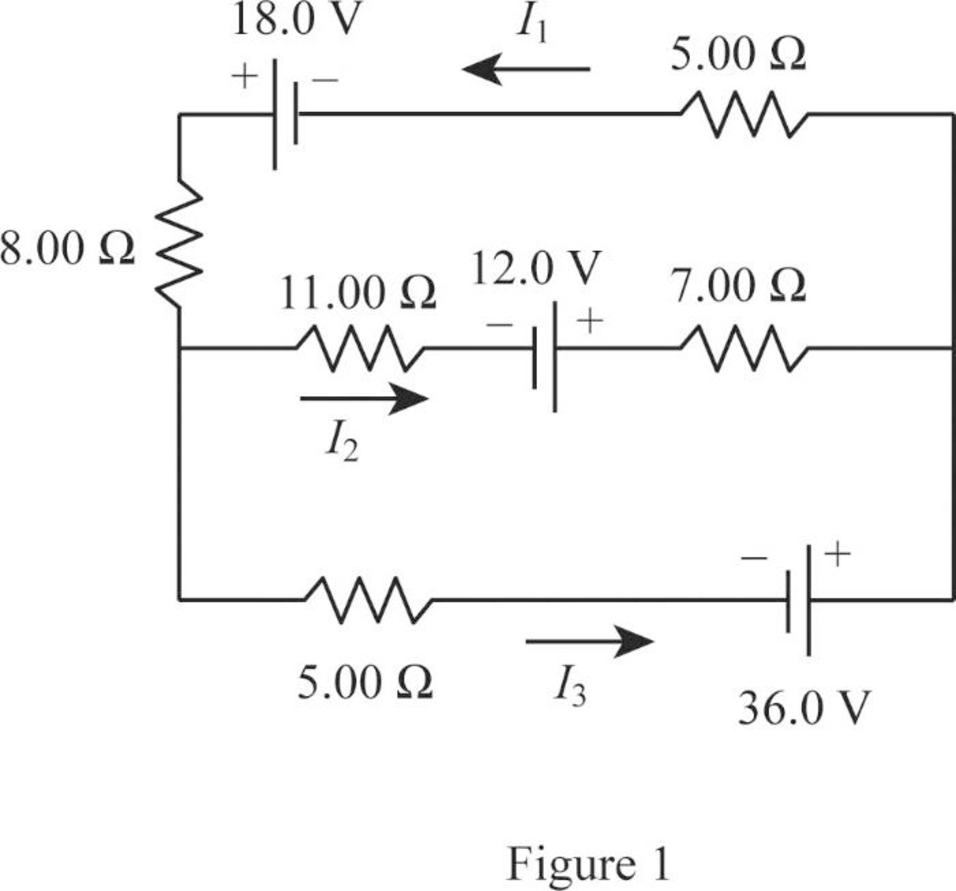
For the circuit shown in Figure P21.50, we wish to find the currents I1, I2, and I3. Use Kirchhoff’s rules to obtain equations for (a) the upper loop, (b) the lower loop, and (c) the junction on the left side. In each case, suppress units for clarity and simplify, combining the terms. (d) Solve the junction equation for I3. (e) Using the equation found in part (d), eliminate I3 from the equation found in part (b). (f) Solve the equations found in parts (a) and (e) simultaneously for the two unknowns I1 and I2. (g) Substitute the answers found in part (f) into the junction equation found in part (d), solving for I3. (h) What is the significance of the negative answer for I2?
Figure P21.50

(a)
The equations for the upper loop in the circuit diagram.
Answer to Problem 50P
The equation for the upper loop is
Explanation of Solution

Write the expression for the Kirchhoff’s loop rule for the upper loop going counter clockwise.
Conclusion:
Therefore, the equation for the upper loop is
(b)
The equations for the lower loop in the circuit diagram.
Answer to Problem 50P
The equation for the lower loop is
Explanation of Solution
Write the expression for the Kirchhoff’s loop rule for the lower loop going counter clockwise.
Conclusion:
Therefore, the equation for the lower loop is
(c)
The equation of the junction on the left side in the circuit diagram.
Answer to Problem 50P
The equation of the junction in the left side is
Explanation of Solution
Write the expression for the Kirchhoff’s junction rule for the junction on the left side in the circuit.
Conclusion:
Therefore, the equation of the junction in the left side is
(d)
The equation for
Answer to Problem 50P
The equation for
Explanation of Solution
Use equation (III) to solve for
Conclusion:
Therefore, the equation for
(e)
The equation of the lower loop without using
Answer to Problem 50P
The equation of the lower loop without using
Explanation of Solution
Use equation (IV) in (II) to solve for the lower without using
Conclusion:
Therefore, the equation of the lower loop without using
(f)
The value of current
Answer to Problem 50P
The value of current
Explanation of Solution
Use equation (V) to solve for
Use equation (VI) in (I) to solve for
Use equation (VII) in (I) to solve for
Conclusion:
Therefore, the value of current
(g)
The value of current
Answer to Problem 50P
The value of current
Explanation of Solution
Use equation (VIII) and (VII) in (IV) to solve for
Conclusion:
Therefore, the value of current
(h)
The significance of negative sign in the current
Answer to Problem 50P
The negative sign for
Explanation of Solution
The negative sign in the value of the current
Conclusion:
Therefore, the negative sign for
Want to see more full solutions like this?
Chapter 21 Solutions
Principles of Physics: A Calculus-Based Text
- The character Min Min from Arms was a DLC character added to Super Smash Bros. Min Min’s arms are large springs, with a spring constant of 8.53 ⋅ 10^3 N/m, which she uses to punch and fling away her opponents. Min Min pushes her spring arm against Steve, who is not moving, compressing it 1.20 m as shown in figure A. Steve has a mass of 81.6 kg. Assuming she uses only the spring to launch Steve, how fast is Steve moving when the spring is no longer compressed? As Steve goes flying away he goes over the edge of the level, as shown in figure C. What is the magnitude of Steve’s velocity when he is 2.00 m below where he started?arrow_forwardSlinky dog whose middle section is a giant spring with a spring constant of 10.9 N/m. Woody, who has a mass of 0.412 kg, grabs onto the tail end of Slink and steps off the bed with no initial velocity and reaches the floor right as his velocity hits zero again. How high is the bed? What is Woody’s velocity halfway down? Enter just the magnitude of velocity.arrow_forwardNo chatgpt pls will upvotearrow_forward
- A positive charge of 91 is located 5.11 m to the left of a negative charge 92. The charges have different magnitudes. On the line through the charges, the net electric field is zero at a spot 2.90 m to the right of the negative charge. On this line there are also two spots where the potential is zero. (a) How far to the left of the negative charge is one spot? (b) How far to the right of the negative charge is the other?arrow_forwardA charge of -3.99 μC is fixed in place. From a horizontal distance of 0.0423 m, a particle of mass 7.31 x 10³ kg and charge -9.76 µC is fired with an initial speed of 84.1 m/s directly toward the fixed charge. How far does the particle travel before its speed is zero?arrow_forwarda) What is the minimum tension in N that the cable must be able to support without breaking? Assume the cable is massless. T = b) If the cable can only support a tension of 10,000 N what is the highest mass the ball can have in kg? mm =arrow_forward
- Curve Fitter CURVE FITTER Open Update Fit Save New Exclusion Rules Select Validation Data Polynomial Exponential Logarithmic Auto Fourier Fit Fit Duplicate Data Manual FILE DATA FIT TYPE FIT Harmonic Motion X us 0.45 mi ce 0.4 0.35 0.3 0.25 0.2 Residuals Plot Contour Plot Plot Prediction Bounds None VISUALIZATION Colormap Export PREFERENCES EXPORT Fit Options COA Fourier Equation Fit Plot x vs. t -Harmonic Motion a0+ a1*cos(x*w) + b1*sin(x*w) Number of terms Center and scale 1 ▸ Advanced Options Read about fit options Results Value Lower Upper 0.15 a0 0.1586 0.1551 0.1620 a1 0.0163 0.0115 0.0211 0.1 b1 0.0011 -0.0093 0.0115 W 1.0473 0.9880 1.1066 2 8 10 t 12 14 16 18 20 Goodness of Fit Value Table of Fits SSE 0.2671 Fit State Fit name Data Harmonic Motion x vs. t Fit type fourier1 R-square 0.13345 SSE DFE 0.26712 296 Adj R-sq 0.12467 RMSE 0.030041 # Coeff Valic R-square 0.1335 4 DFE 296.0000 Adj R-sq 0.1247 RMSE 0.0300arrow_forwardWhat point on the spring or different masses should be the place to measure the displacement of the spring? For instance, should you measure to the bottom of the hanging masses?arrow_forwardLet's assume that the brightness of a field-emission electron gun is given by β = 4iB π² d²α² a) Assuming a gun brightness of 5x10⁸ A/(cm²sr), if we want to have an electron beam with a semi-convergence angle of 5 milliradian and a probe current of 1 nA, What will be the effective source size? (5 points) b) For the same electron gun, plot the dependence of the probe current on the parameter (dpa) for α = 2, 5, and 10 milliradian, respectively. Hint: use nm as the unit for the electron probe size and display the three plots on the same graph. (10 points)arrow_forward
- i need step by step clear answers with the free body diagram clearlyarrow_forwardNo chatgpt pls will upvotearrow_forwardReview the data in Data Table 1 and examine the standard deviations and 95% Margin of Error calculations from Analysis Questions 3 and 4 for the Acceleration of the 1st Based on this information, explain whether Newton’s Second Law of Motion, Equation 1, was verified for your 1st Angle. Equation: SF=ma Please help with explaining the information I collected from a lab and how it relates to the equation and Newton's Second Law. This will help with additional tables in the lab. Thanks!arrow_forward

 Principles of Physics: A Calculus-Based TextPhysicsISBN:9781133104261Author:Raymond A. Serway, John W. JewettPublisher:Cengage Learning
 Physics for Scientists and Engineers, Technology ...PhysicsISBN:9781305116399Author:Raymond A. Serway, John W. JewettPublisher:Cengage Learning
 College PhysicsPhysicsISBN:9781305952300Author:Raymond A. Serway, Chris VuillePublisher:Cengage Learning
 College PhysicsPhysicsISBN:9781285737027Author:Raymond A. Serway, Chris VuillePublisher:Cengage Learning
 College PhysicsPhysicsISBN:9781938168000Author:Paul Peter Urone, Roger HinrichsPublisher:OpenStax College


