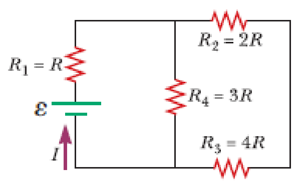
Four resistors are connected to a battery as shown in Figure P21.40. The current in the battery is I, the battery emf is ε, and the resistor values are R1 = R, R2 = 2R, R3 = 4R, and R4 = 3R. (a) Rank the resistors according to the potential difference across them, from largest to smallest. Note any cases of equal potential differences. (b) Determine the potential difference across each resistor in terms of ε. (c) Rank the resistors according to the current in them, from largest to smallest. Note any cases of equal currents. (d) Determine the current in each resistor in terms of I. (e) If R3 is increased, what happens to the current in each of the resistors? (f) In the limit that R3 → ∞, what are the new values of the current in each resistor in terms of I, the original current in the battery?

Figure P21.40
(a)
The rank of the resistors according to the potential difference across them from largest to smallest.
Answer to Problem 40P
The rank the resistors according to the potential difference across them from largest to smallest is
Explanation of Solution
The resistor
Write the equivalent resistance for the combination of resistors
Here,
The
Write the resistance of the circuit.
Here,
In series combinations, the potential is dropped in proportion to the resistance.
Resistor
Conclusion:
Therefore, the rank of resistors according to the potential difference across them from largest to smallest is
(b)
The potential difference across each resistors in terms of
Answer to Problem 40P
The potential difference across
Explanation of Solution
In series combinations, the potential is dropped in proportion to the resistance.
Resistor
Conclusion:
Therefore, the potential difference across
(c)
The rank of the resistors according to the current in them from largest to smallest.
Answer to Problem 40P
The rank of the resistors according to the current in them from largest to smallest is
Explanation of Solution
All the current will pass through the resistor
The ranking of the resistors according to the current in them from largest to smallest is
Conclusion:
Therefore, the rank resistors according to the current in them from largest to smallest is
(d)
The current in each resistor in terms of
Answer to Problem 40P
The current in
Explanation of Solution
The resistor
As a result, the current in
Conclusion:
Therefore, the current in
(e)
If
Answer to Problem 40P
The value of current
Explanation of Solution
As the value of resistance
Conclusion:
Therefore, the value of current
(f)
If
Answer to Problem 40P
The current
Explanation of Solution
If the
Conclusion:
Therefore, the current
Want to see more full solutions like this?
Chapter 21 Solutions
Principles of Physics: A Calculus-Based Text
- please answer this asap!!!!arrow_forwardRT = 4.7E-30 18V IT = 2.3E-3A+ 12 38Ω ли 56Ω ли r5 27Ω ли r3 28Ω r4 > 75Ω r6 600 0.343V 75.8A Now figure out how much current in going through the r4 resistor. |4 = unit And then use that current to find the voltage drop across the r resistor. V4 = unitarrow_forward7 Find the volume inside the cone z² = x²+y², above the (x, y) plane, and between the spheres x²+y²+z² = 1 and x² + y²+z² = 4. Hint: use spherical polar coordinates.arrow_forward
- ганм Two long, straight wires are oriented perpendicular to the page, as shown in the figure(Figure 1). The current in one wire is I₁ = 3.0 A, pointing into the page, and the current in the other wire is 12 4.0 A, pointing out of the page. = Find the magnitude and direction of the net magnetic field at point P. Express your answer using two significant figures. VO ΜΕ ΑΣΦ ? Figure P 5.0 cm 5.0 cm ₁ = 3.0 A 12 = 4.0 A B: μΤ You have already submitted this answer. Enter a new answer. No credit lost. Try again. Submit Previous Answers Request Answer 1 of 1 Part B X Express your answer using two significant figures. ΜΕ ΑΣΦ 0 = 0 ? below the dashed line to the right P You have already submitted this answer. Enter a new answer. No credit lost. Try again.arrow_forwardAn infinitely long conducting cylindrical rod with a positive charge λ per unit length is surrounded by a conducting cylindrical shell (which is also infinitely long) with a charge per unit length of −2λ and radius r1, as shown in the figure. What is σinner, the surface charge density (charge per unit area) on the inner surface of the conducting shell? What is σouter, the surface charge density on the outside of the conducting shell? (Recall from the problem statement that the conducting shell has a total charge per unit length given by −2λ.)arrow_forwardA small conducting spherical shell with inner radius aa and outer radius b is concentric with a larger conducting spherical shell with inner radius c and outer radius d (Figure 1). The inner shell has total charge +2q, and the outer shell has charge −2q. What's the total charge on the inner surface of the small shell? What's the total charge on the outer surface of the small shell? What's the total charge on the inner surface of the large shell? What's the total charge on the outer surface of the large shell?arrow_forward
 Physics for Scientists and EngineersPhysicsISBN:9781337553278Author:Raymond A. Serway, John W. JewettPublisher:Cengage Learning
 Physics for Scientists and Engineers with Modern ...PhysicsISBN:9781337553292Author:Raymond A. Serway, John W. JewettPublisher:Cengage Learning
 Principles of Physics: A Calculus-Based TextPhysicsISBN:9781133104261Author:Raymond A. Serway, John W. JewettPublisher:Cengage Learning
 Physics for Scientists and Engineers: Foundations...PhysicsISBN:9781133939146Author:Katz, Debora M.Publisher:Cengage Learning
 Physics for Scientists and Engineers, Technology ...PhysicsISBN:9781305116399Author:Raymond A. Serway, John W. JewettPublisher:Cengage Learning
 College PhysicsPhysicsISBN:9781305952300Author:Raymond A. Serway, Chris VuillePublisher:Cengage Learning


