
Basic Engineering Circuit Analysis
11th Edition
ISBN: 9781118539293
Author: J. David Irwin, R. Mark Nelms
Publisher: WILEY
expand_more
expand_more
format_list_bulleted
Concept explainers
Videos
Textbook Question
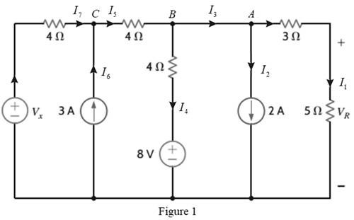
Chapter 2, Problem 91P
If
Expert Solution & Answer
Want to see the full answer?
Check out a sample textbook solution
Students have asked these similar questions
How can I design a socket for a trolley headlight? What parameters should I measure? The only thing I have is the headlight itself, and I don’t have any information about its power, current, or voltage rating. The power source is 120 V, and my goal is simply to get the headlight to turn on.I’m not sure where to start or what to measure. Any recommendations would be greatly appreciated!
Figure 2
3) *** The circuit of Figure 3 is designed with W/L = 20/0.18, λ= 0, and ID = 0.25 mA.
(Optional- 20 points)
a) Compute the required gate bias voltage.
b) With such a gate voltage, how much can W/L be increased while M1 remains in
saturation? What is the maximum voltage gain that can be achieved as W/L
increases?
VDD = 1.8 V
RD 2k
- Vout
Vin M₁
Figure 3
1) Rs = 4kQ, R₁ = 850 kQ, R₂ = 350 kQ, and R₁ = 4 kQ. The transistor parameters are
VTP = -12 V, K'p = 40 µA / V², W/L = 80, and λ = 0.05 V-1. (50 Points)
a) Determine IDQ and VSDQ.
b) Find the small signal voltage gain. (Av)
c) Determine the small signal circuit transconductance gain. (Ag = io/vi)
d) Find the small signal output resistance.
VDD = 10 V
2';
www
www
Figure 1
Сс
Chapter 2 Solutions
Basic Engineering Circuit Analysis
Ch. 2 - Determine the current and power dissipated in the...Ch. 2 - Determine the voltage across the resistor in Fig....Ch. 2 - In the network in Fig. P2.3, the power absorbed by...Ch. 2 - In the network in Fig. P2.4, the power absorbed by...Ch. 2 - A model for a standard two D-cell flashlight is...Ch. 2 - An automobile uses two halogen headlights...Ch. 2 - Many years ago a string of Christmas tree lights...Ch. 2 - Find I1,I2, and I3 in the network in Fig.P2.8.Ch. 2 - Find I1 in the network in Fig.P2.9.Ch. 2 - Find I1 in the network in Fig.P2.10.
Ch. 2 - Find I1 in the circuit in Fig.P2.11.Ch. 2 - Find I0 and I1 in the circuit in Fig.P2.12.Ch. 2 - Find Ix,Iy, and Iz in the network in Fig.P2.13.Ch. 2 - Find Ix in the circuit in Fig.P2.14.Ch. 2 - Find Ix in the network in Fig. P2.15.Ch. 2 - Find I1 in the network in Fig. P2.16.Ch. 2 - Find Vbd in the circuit in Fig. P2.17.Ch. 2 - Find I1 in the circuit in Fig. P2.18.Ch. 2 - Find I1,I2, and I3 in the network in Fig. P2.19.Ch. 2 - Find Vfb and Vec in the circuit in Fig. P2.20.Ch. 2 - Given the circuit diagram in Fig. P2.21, find the...Ch. 2 - Find VBE and VDA in the circuit in Fig. P2.22.Ch. 2 - Find Vx and Vy in the circuit in Fig. P2.23.Ch. 2 - Find Vac in the circuit in Fig. P2.24.Ch. 2 - Find Vad and Vce in the circuit in Fig. P2.25.Ch. 2 - Find Vo in the circuit in Fig. P2.26.Ch. 2 - Find V1,V2, and V3 in the network in Fig. P2.27.Ch. 2 - Find Vo in the network in Fig. P2.28.Ch. 2 - Find V1,V2, and V3 in the network in Fig. P2.29.Ch. 2 - If Vo=3V in the circuit in Fig. P2.30, find Vs.Ch. 2 - Find the power supplied by each source in the...Ch. 2 - The 10-V source absorbs 2.5-mW of power. Calculate...Ch. 2 - Find Vbd in the network in Fig. P2.33.Ch. 2 - Find V1 in the network in Fig. P2.34.Ch. 2 - Find the power absorbed by the dependent source in...Ch. 2 - In the network in Fig. P2.36, find Vx,VAE, and VBD...Ch. 2 - In the network in Fig. P2.37, find VS if VEB=6V.Ch. 2 - Find VS in the circuit in Fig. P2.38, if VBE=18V.Ch. 2 - Find VA in the network in Fig. P2.39.Ch. 2 - If the 12-V source in the network in Fig. P2.40...Ch. 2 - If VX=12V in the network in Fig. P2.41, find VS...Ch. 2 - Calculate the power absorbed by the dependent...Ch. 2 - Find VA and VO in the circuit in Fig. P2.43.Ch. 2 - Find VO and the power absorbed by the 2k resistor...Ch. 2 - Find the power absorbed or supplied by the 12-V...Ch. 2 - Find Vo in the circuit in Fig. P2.46.Ch. 2 - Find I0 in the network in Fig. P2.47.Ch. 2 - Find Io in the network in Fig. P2.48.Ch. 2 - Find the power supplied by each source in the...Ch. 2 - Find the current IA in the circuit in Fig. P2.50.Ch. 2 - Find IS in the network in Fig. P2.51.Ch. 2 - Find Io in the circuit in Fig. P2.52.Ch. 2 - Find Io in the network in Fig. P2.53.Ch. 2 - Find Vo in the circuit in Fig. P2.54.Ch. 2 - Find Vo in the network in Fig. P2.55.Ch. 2 - Find Io in the network in Fig. P2.56.Ch. 2 - Find Io in the network in Fig. P2.57.Ch. 2 - Find IL in the circuit in Fig. P2.58.Ch. 2 - Find RAB in the network in Fig. P2.59.Ch. 2 - Find RAB in the circuit in Fig. P2.60.Ch. 2 - Find RAB in the circuit in Fig. P2.61.Ch. 2 - Find RAB in the network in Fig. P2.62.Ch. 2 - Find RAB in the circuit in Fig. P2.63.Ch. 2 - Find RAB in the circuit in Fig. P2.64.Ch. 2 - Find RAB in the circuit in Fig. P2.65.Ch. 2 - Find the equivalent resistance Req in the network...Ch. 2 - Find RAB in the network in Fig. P2.67.Ch. 2 - Given the resistor configuration shown in Fig....Ch. 2 - Determine the total resistance, RT, in the circuit...Ch. 2 - Determine the total resistance, RT, in the circuit...Ch. 2 - Determine the total resistance, RT, in the circuit...Ch. 2 - Find the power supplied by the source in the...Ch. 2 - Find I1 and Vo in the circuit in Fig. P2.73.Ch. 2 - Find I1 and Vo in the circuit in Fig. P2.74.Ch. 2 - Find Vab and Vdc in the circuit in Fig. P2.75.Ch. 2 - Find Io in the network in Fig. P2.76.Ch. 2 - Find Io in the circuit in Fig. P2.77.Ch. 2 - Find V1 in the network in Fig. P2.78.Ch. 2 - Find Vab in the circuit in Fig. P2.79.Ch. 2 - Find Vab in the network in Fig. P2.80.Ch. 2 - Find I1,I2, and V1 in the circuit in Fig. P2.81.Ch. 2 - Determine Vo in the network in Fig. P2.82.Ch. 2 - Calculate VAB in Fig. P2.83.Ch. 2 - Find Io in the network in Fig. P2.84 if all...Ch. 2 - Find Io in the circuit in Fig. P2.85.Ch. 2 - Determine the power supplied by the 36-V source in...Ch. 2 - Find the power supplied by the current source in...Ch. 2 - In the network in Fig. P2.88, V1=12V. Find VS.Ch. 2 - In the circuit in Fig. P2.89, Vo=2V. Find IS.Ch. 2 - In the network in Fig. P2.90, V1=14V. Find VS.Ch. 2 - If VR=15V, find VX in Fig. P2.91.Ch. 2 - Find the value of IA in the network in Fig. P2.92.Ch. 2 - If V1=5V in the circuit in Fig. P2.93, find IS.Ch. 2 - Given that Vo=4V in the network in Fig. P2.94,...Ch. 2 - Find the value of VS in the network in Fig. P2.95...Ch. 2 - In the network in Fig. P2.96, VO=6V. Find IS.Ch. 2 - Find the value of V1 in the network in Fig. P2.97...Ch. 2 - Find the value of IA in the circuit in Fig. P2.98.Ch. 2 - If the power supplied by the 2-A current source is...Ch. 2 - The 40-V source in the circuit in Fig. P2.100 is...Ch. 2 - Find the value of the current source IA in the...Ch. 2 - Given Io=2mA in the network in Fig. P2.102, find...Ch. 2 - Find the value of Vx in the network in Fig....Ch. 2 - Given Ia=2mA in the circuit in Fig. P2.104, find...Ch. 2 - Given Va in the network in Fig. 2.105, find IA.Ch. 2 - Find the value of Vx in the circuit in Fig. P2.106...Ch. 2 - Find the power absorbed by the network in Fig....Ch. 2 - Find the value of g in the network in Fig. P2.108...Ch. 2 - Find the power supplied by the 24-V source in the...Ch. 2 - Find Io in circuit in Fig. P2.110.Ch. 2 - Find Io in circuit in Fig. P2.111.Ch. 2 - Determine the value of Vo in the network in Fig....Ch. 2 - If Vo in the circuit in Fig. P2.113 is 24 V, find...Ch. 2 - Find the value of VS in the network in Fig....Ch. 2 - Find the power supplied by the 6-mA source in the...Ch. 2 - Find Vo in the circuit in Fig. P2.116.Ch. 2 - Find Vo in the network in Fig. P2.117.Ch. 2 - Find I1 in the network in Fig. P2.118.Ch. 2 - A single-stage transistor amplifier is modeled as...Ch. 2 - Find Io in the circuit in Fig. P2.120.Ch. 2 - Find Vo in the circuit in Fig. P2.121.Ch. 2 - A typical transistor amplifier is shown in Fig....Ch. 2 - Find VX in the network in Fig. P2.123.Ch. 2 - Find Vo in the network in Fig. P2.124.Ch. 2 - Find I1,I2, and I3 in the circuit in Fig. P2.125.Ch. 2 - Find Io in the network in Fig. P2.126.Ch. 2 - Find the power absorbed by the 12-k resistor on...Ch. 2 - Find the power absorbed by the 12-k resistor in...Ch. 2 - Find the value of k in the network in Fig. P2.129...Ch. 2 - If the power absorbed by the 10-V source in Fig....Ch. 2 - If the power supplied by the 2-A current source in...Ch. 2 - What is the power generated by the source in the...Ch. 2 - Find v ah in the circuit in Fig. 2PFE-2. a. 5V c....Ch. 2 - If Req=10.8 in the circuit in Fig. 2PFE-3, what is...Ch. 2 - Find the equivalent resistance of the circuit in...Ch. 2 - The 100-V source is absorbing 50W of power in the...Ch. 2 - Find the power supplied by the 40-V source in the...Ch. 2 - What is the current I0 in the circuit in Fig....Ch. 2 - Find the voltage Vo in the network in Fig. 2PFE-8....Ch. 2 - What is the voltage Vo in the circuit in Fig....Ch. 2 - Find the current Ix in Fig. 2PFE-10. a. 1/2Ac....
Additional Engineering Textbook Solutions
Find more solutions based on key concepts
A surface 12 in. long is to be machined with a flat, solid broach that has a rise per tooth of 0.0047 in. What ...
Degarmo's Materials And Processes In Manufacturing
When displaying a Java applet, the browser invokes the _____ to interpret the bytecode into the appropriate mac...
Web Development and Design Foundations with HTML5 (8th Edition)
What output is produced by the following code? int count = 0; while (count 5) { System.out.println(count); cou...
Java: An Introduction to Problem Solving and Programming (8th Edition)
Find the no-load value of υo in the circuit shown.
Find υo when RL is 150 Ω.
How much power is dissipated in th...
Electric Circuits. (11th Edition)
59. A 100-watt [W] motor (60% efficient) is used to raise a 100-kilogram [kg] toad 5 meters [m] into the air. H...
Thinking Like an Engineer: An Active Learning Approach (4th Edition)
In the following exercises, write a program to carry out the task. The program should use variables for each of...
Introduction To Programming Using Visual Basic (11th Edition)
Knowledge Booster


Learn more about
Need a deep-dive on the concept behind this application? Look no further. Learn more about this topic, electrical-engineering and related others by exploring similar questions and additional content below.Similar questions
- Q13arrow_forward2) The transistor parameters of the NMOS device in the common-gate amplifier in Figure 2 are VTN = 0.4V, K'n = 100 μA / V², and λ=0. (50 points) a) Find RD such that VDSQ = VDs (sat) + 0.25V. b) Determine the transistor W/L ratio such that the small-signal voltage gain is Av=6. c) What is the value of VGSQ? Сс 2 mA Rp T V=-1.8 V V+= 1.8 V Figure 2arrow_forwardCalculate the percent voltage regulation for a three-phase wye-connected 2500 kVA 6600-V turboalternator operating at full-load Unity power factor The per phase synchronous reactance and the armature resistance are 10.4 2 and 0.071 ≤2, respectively?arrow_forward
- Don't use ai to answer I will report you answerarrow_forwardChose the correct answer: 1- A squirrel cage induction motor is not selected when (A) initial cost is the main consideration (B) maintenance cost is to be kept low (C) higher starting torque is the main consideration (D) all above considerations are involved 2- The torque of an induction motor is .............. (A) directly proportional to slip (B) inversely proportional to slip... (C) proportional to the square of the slip (D) none of the above 3- Insertion of resistance in the stator of an induction motor. (A) increases the load torque (B) decreases the starting torque (C) increases the starting torque (D) none of above tool to slip 10 or of the above 4- Increase in the length of air-gap in the induction motor results in the increasing of its (A) air-gap flux (B) magnetizing current (C) speed (D) power factor 5- In cumulatively cascade method for speed controlling, if PA is the number of poles of main motor and PB is the number of poles of auxiliary motor. Then the speed of the set…arrow_forwardChose the correct answer: 1- The resultant flux in stator winding of three-phase induction motor is equal to (A) Maximum value of flux due to any phase (B) Twice of the maximum value of flux due to any phase. (C) 0.5 times the maximum value of flux due to any phase (D) 1.5 times the maximum value of flux due to any phase 2- Which one of the following starters cannot be used for 3-phase, star - connected, slip-ring induction motor? (A) Auto-transformer starter (B) Star-delta starter (C) Direct-on-line starter (D) Rotor resistance starter 3- The crawling in the induction motor is caused by.............. (A) low voltage supply (B) high loads (D) improper design of the machine (C) harmonics developed in the motor 4- The 'cogging' of an induction motor can be avoided by........... (A) good ventilation (B) using DOL starter (C) star-connecting of stator winding (D) having number of rotor slots more or less than the number of stator slots 5- The method which can be used for the speed control…arrow_forward
arrow_back_ios
SEE MORE QUESTIONS
arrow_forward_ios
Recommended textbooks for you
 Introductory Circuit Analysis (13th Edition)Electrical EngineeringISBN:9780133923605Author:Robert L. BoylestadPublisher:PEARSON
 Delmar's Standard Textbook Of ElectricityElectrical EngineeringISBN:9781337900348Author:Stephen L. HermanPublisher:Cengage Learning
 Programmable Logic ControllersElectrical EngineeringISBN:9780073373843Author:Frank D. PetruzellaPublisher:McGraw-Hill Education
 Fundamentals of Electric CircuitsElectrical EngineeringISBN:9780078028229Author:Charles K Alexander, Matthew SadikuPublisher:McGraw-Hill Education
 Electric Circuits. (11th Edition)Electrical EngineeringISBN:9780134746968Author:James W. Nilsson, Susan RiedelPublisher:PEARSON
 Engineering ElectromagneticsElectrical EngineeringISBN:9780078028151Author:Hayt, William H. (william Hart), Jr, BUCK, John A.Publisher:Mcgraw-hill Education,
Introductory Circuit Analysis (13th Edition)
Electrical Engineering
ISBN:9780133923605
Author:Robert L. Boylestad
Publisher:PEARSON
Delmar's Standard Textbook Of Electricity
Electrical Engineering
ISBN:9781337900348
Author:Stephen L. Herman
Publisher:Cengage Learning
Programmable Logic Controllers
Electrical Engineering
ISBN:9780073373843
Author:Frank D. Petruzella
Publisher:McGraw-Hill Education
Fundamentals of Electric Circuits
Electrical Engineering
ISBN:9780078028229
Author:Charles K Alexander, Matthew Sadiku
Publisher:McGraw-Hill Education
Electric Circuits. (11th Edition)
Electrical Engineering
ISBN:9780134746968
Author:James W. Nilsson, Susan Riedel
Publisher:PEARSON
Engineering Electromagnetics
Electrical Engineering
ISBN:9780078028151
Author:Hayt, William H. (william Hart), Jr, BUCK, John A.
Publisher:Mcgraw-hill Education,
Current Divider Rule; Author: Neso Academy;https://www.youtube.com/watch?v=hRU1mKWUehY;License: Standard YouTube License, CC-BY