
Basic Engineering Circuit Analysis
11th Edition
ISBN: 9781118539293
Author: J. David Irwin, R. Mark Nelms
Publisher: WILEY
expand_more
expand_more
format_list_bulleted
Concept explainers
Videos
Textbook Question
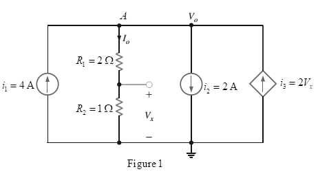
Chapter 2, Problem 120P
Find
Expert Solution & Answer
Want to see the full answer?
Check out a sample textbook solution
Students have asked these similar questions
3. Describe the function of PLL circuit.
4. Describe the function of bandpass filter.
ASK Modulator/Demodulator
U1
VD Signal in
VT out
X1
W
R1
VC Carrier in
w
x2
100K
3
Y1
4
Y2 AD633 Z
VR1
10K
VR1
Multiplier(1)
I
U2
Vx out
X1
W
R3
2
w
x2
In2
100K
3
۲۱
I
Y2 AD633
Z
VR2
R2
10K
C4
100K
VR2
Multiplier(2)
+5V
200p
R5
R6
R101K
ww w
2.7K
22K
1N4148
D1
559
VE out
D+
In(ac)
6 0H
200p
HH
6
VLP out
Vo out
U3
VR
0.01
0.1u
R8
VR3
ww
50K
Envelope Detector
10K
U3
LF356
VR3
LPF
U4Σ
LM311
Comparator
U5
PLL in CS
HH
14 SIGN IN
0.1u
6 CIA
PC1OUT 2
PULSES
PHASE(2)
COMPARATOR OUT 13.
C10
HT
150p R16
ww
R12
VSO
C6
200p
VCO OUT 4
IK
in
R14
C9
18K
10 O
w
7 Cle
H
VLO out
6
15K
VCO
150p
06
11 R1
CD4046
VCO IN 9
VR5
1K
12 R2
0.0047u
C7
I
Demod
C8 out
10
SOURCE
FOLLOWER
R11
100K
INH
COMP IN
5
3
VR4
+5V+12V GND-12V
о
HTO
0.1u
R13
10K
I
PL
VR5
Figure 18-10 KL-94005 module
R15
U6Σ
OP37
BPF
DUC
1. Is the waveform on VT out terminal an ASK modulated signal?
TS
PROD
2. Is the waveform on VT out terminal an OOK modulated signal?
ASK Modulator/Demodulator
U1
VD Signal in
VT out
X1
W
R1
VC Carrier in
w
x2
100K
3
Y1
4
Y2 AD633 Z
VR1
10K
VR1
Multiplier(1)
I
U2
Vx out
X1
W
R3
2
w
x2
In2
100K
3
۲۱
I
Y2 AD633
Z
VR2
R2
10K
C4
100K
VR2
Multiplier(2)
+5V
200p
R5
R6
R101K
ww w
2.7K
22K
1N4148
D1
559
VE out
D+
In(ac)
6 0H
200p
HH
6
VLP out
Vo out
U3
VR
0.01
0.1u
R8
VR3
ww
50K
Envelope Detector
10K
U3
LF356
VR3
LPF
U4Σ
LM311
Comparator
U5
PLL in CS
HH
14 SIGN IN
PC1OUT 2
0.1u
6 CIA
PULSES
PHASE(2)
COMPARATOR
OUT 13
C10
HT
150p R16
ww
R12
VSO
18K
C6
200p
VCO OUT 4
IK
in
R14
C9
10 O
w
H
VLO out
6
7 Cle
15K
VCO
150p
06
11 R1
CD4046
VCO IN 9
VR5
1K
12 R2
0.0047u
C7
I
Demod
C8 out
10
SOURCE
FOLLOWER
R11
100K
INH
COMP IN
5
3
VR4
+5V+12V GND-12V
о
HTO
0.1u
R13
10K
I
PL
Figure 18-10 KL-94005 module
VR5
R15
U6Σ
OP37
BPF
h
e
6. Discuss the relationship between Vx out and VLP out signals.
7. Describe the function of comparator.
ASK Modulator/Demodulator
U1
VD Signal in
VT out
X1
W
R1
VC Carrier in
w
x2
100K
3
Y1
4
Y2 AD633 Z
VR1
10K
VR1
Multiplier(1)
I
U2
Vx out
X1
W
R3
2
w
x2
In2
100K
3
۲۱
I
Y2 AD633
Z
VR2
R2
10K
C4
100K
VR2
Multiplier(2)
+5V
200p
R5
R6
R101K
ww w
2.7K
22K
1N4148
D1
559
VE out
D+
In(ac)
6 0H
200p
HH
6
VLP out
Vo out
U3
VR
0.01
0.1u
R8
VR3
ww
50K
Envelope Detector
10K
U3
LF356
VR3
LPF
U4Σ
LM311
Comparator
U5
PLL in CS
HH
14 SIGN IN
0.1u
6 CIA
PC1OUT 2
PULSES
PHASE(2)
COMPARATOR OUT 13.
C10
HT
150p R16
ww
R12
VSO
C6
200p
VCO OUT 4
IK
in
R14
C9
18K
10 O
w
7 Cle
H
VLO out
6
15K
VCO
150p
06
11 R1
CD4046
VCO IN 9
VR5
1K
12 R2
0.0047u
C7
I
Demod
C8 out
10
SOURCE
FOLLOWER
R11
100K
INH
COMP IN
5
3
VR4
+5V+12V GND-12V
о
HTO
0.1u
R13
10K
I
PL
VR5
Figure 18-10 KL-94005 module
R15
U6Σ
OP37
BPF
Chapter 2 Solutions
Basic Engineering Circuit Analysis
Ch. 2 - Determine the current and power dissipated in the...Ch. 2 - Determine the voltage across the resistor in Fig....Ch. 2 - In the network in Fig. P2.3, the power absorbed by...Ch. 2 - In the network in Fig. P2.4, the power absorbed by...Ch. 2 - A model for a standard two D-cell flashlight is...Ch. 2 - An automobile uses two halogen headlights...Ch. 2 - Many years ago a string of Christmas tree lights...Ch. 2 - Find I1,I2, and I3 in the network in Fig.P2.8.Ch. 2 - Find I1 in the network in Fig.P2.9.Ch. 2 - Find I1 in the network in Fig.P2.10.
Ch. 2 - Find I1 in the circuit in Fig.P2.11.Ch. 2 - Find I0 and I1 in the circuit in Fig.P2.12.Ch. 2 - Find Ix,Iy, and Iz in the network in Fig.P2.13.Ch. 2 - Find Ix in the circuit in Fig.P2.14.Ch. 2 - Find Ix in the network in Fig. P2.15.Ch. 2 - Find I1 in the network in Fig. P2.16.Ch. 2 - Find Vbd in the circuit in Fig. P2.17.Ch. 2 - Find I1 in the circuit in Fig. P2.18.Ch. 2 - Find I1,I2, and I3 in the network in Fig. P2.19.Ch. 2 - Find Vfb and Vec in the circuit in Fig. P2.20.Ch. 2 - Given the circuit diagram in Fig. P2.21, find the...Ch. 2 - Find VBE and VDA in the circuit in Fig. P2.22.Ch. 2 - Find Vx and Vy in the circuit in Fig. P2.23.Ch. 2 - Find Vac in the circuit in Fig. P2.24.Ch. 2 - Find Vad and Vce in the circuit in Fig. P2.25.Ch. 2 - Find Vo in the circuit in Fig. P2.26.Ch. 2 - Find V1,V2, and V3 in the network in Fig. P2.27.Ch. 2 - Find Vo in the network in Fig. P2.28.Ch. 2 - Find V1,V2, and V3 in the network in Fig. P2.29.Ch. 2 - If Vo=3V in the circuit in Fig. P2.30, find Vs.Ch. 2 - Find the power supplied by each source in the...Ch. 2 - The 10-V source absorbs 2.5-mW of power. Calculate...Ch. 2 - Find Vbd in the network in Fig. P2.33.Ch. 2 - Find V1 in the network in Fig. P2.34.Ch. 2 - Find the power absorbed by the dependent source in...Ch. 2 - In the network in Fig. P2.36, find Vx,VAE, and VBD...Ch. 2 - In the network in Fig. P2.37, find VS if VEB=6V.Ch. 2 - Find VS in the circuit in Fig. P2.38, if VBE=18V.Ch. 2 - Find VA in the network in Fig. P2.39.Ch. 2 - If the 12-V source in the network in Fig. P2.40...Ch. 2 - If VX=12V in the network in Fig. P2.41, find VS...Ch. 2 - Calculate the power absorbed by the dependent...Ch. 2 - Find VA and VO in the circuit in Fig. P2.43.Ch. 2 - Find VO and the power absorbed by the 2k resistor...Ch. 2 - Find the power absorbed or supplied by the 12-V...Ch. 2 - Find Vo in the circuit in Fig. P2.46.Ch. 2 - Find I0 in the network in Fig. P2.47.Ch. 2 - Find Io in the network in Fig. P2.48.Ch. 2 - Find the power supplied by each source in the...Ch. 2 - Find the current IA in the circuit in Fig. P2.50.Ch. 2 - Find IS in the network in Fig. P2.51.Ch. 2 - Find Io in the circuit in Fig. P2.52.Ch. 2 - Find Io in the network in Fig. P2.53.Ch. 2 - Find Vo in the circuit in Fig. P2.54.Ch. 2 - Find Vo in the network in Fig. P2.55.Ch. 2 - Find Io in the network in Fig. P2.56.Ch. 2 - Find Io in the network in Fig. P2.57.Ch. 2 - Find IL in the circuit in Fig. P2.58.Ch. 2 - Find RAB in the network in Fig. P2.59.Ch. 2 - Find RAB in the circuit in Fig. P2.60.Ch. 2 - Find RAB in the circuit in Fig. P2.61.Ch. 2 - Find RAB in the network in Fig. P2.62.Ch. 2 - Find RAB in the circuit in Fig. P2.63.Ch. 2 - Find RAB in the circuit in Fig. P2.64.Ch. 2 - Find RAB in the circuit in Fig. P2.65.Ch. 2 - Find the equivalent resistance Req in the network...Ch. 2 - Find RAB in the network in Fig. P2.67.Ch. 2 - Given the resistor configuration shown in Fig....Ch. 2 - Determine the total resistance, RT, in the circuit...Ch. 2 - Determine the total resistance, RT, in the circuit...Ch. 2 - Determine the total resistance, RT, in the circuit...Ch. 2 - Find the power supplied by the source in the...Ch. 2 - Find I1 and Vo in the circuit in Fig. P2.73.Ch. 2 - Find I1 and Vo in the circuit in Fig. P2.74.Ch. 2 - Find Vab and Vdc in the circuit in Fig. P2.75.Ch. 2 - Find Io in the network in Fig. P2.76.Ch. 2 - Find Io in the circuit in Fig. P2.77.Ch. 2 - Find V1 in the network in Fig. P2.78.Ch. 2 - Find Vab in the circuit in Fig. P2.79.Ch. 2 - Find Vab in the network in Fig. P2.80.Ch. 2 - Find I1,I2, and V1 in the circuit in Fig. P2.81.Ch. 2 - Determine Vo in the network in Fig. P2.82.Ch. 2 - Calculate VAB in Fig. P2.83.Ch. 2 - Find Io in the network in Fig. P2.84 if all...Ch. 2 - Find Io in the circuit in Fig. P2.85.Ch. 2 - Determine the power supplied by the 36-V source in...Ch. 2 - Find the power supplied by the current source in...Ch. 2 - In the network in Fig. P2.88, V1=12V. Find VS.Ch. 2 - In the circuit in Fig. P2.89, Vo=2V. Find IS.Ch. 2 - In the network in Fig. P2.90, V1=14V. Find VS.Ch. 2 - If VR=15V, find VX in Fig. P2.91.Ch. 2 - Find the value of IA in the network in Fig. P2.92.Ch. 2 - If V1=5V in the circuit in Fig. P2.93, find IS.Ch. 2 - Given that Vo=4V in the network in Fig. P2.94,...Ch. 2 - Find the value of VS in the network in Fig. P2.95...Ch. 2 - In the network in Fig. P2.96, VO=6V. Find IS.Ch. 2 - Find the value of V1 in the network in Fig. P2.97...Ch. 2 - Find the value of IA in the circuit in Fig. P2.98.Ch. 2 - If the power supplied by the 2-A current source is...Ch. 2 - The 40-V source in the circuit in Fig. P2.100 is...Ch. 2 - Find the value of the current source IA in the...Ch. 2 - Given Io=2mA in the network in Fig. P2.102, find...Ch. 2 - Find the value of Vx in the network in Fig....Ch. 2 - Given Ia=2mA in the circuit in Fig. P2.104, find...Ch. 2 - Given Va in the network in Fig. 2.105, find IA.Ch. 2 - Find the value of Vx in the circuit in Fig. P2.106...Ch. 2 - Find the power absorbed by the network in Fig....Ch. 2 - Find the value of g in the network in Fig. P2.108...Ch. 2 - Find the power supplied by the 24-V source in the...Ch. 2 - Find Io in circuit in Fig. P2.110.Ch. 2 - Find Io in circuit in Fig. P2.111.Ch. 2 - Determine the value of Vo in the network in Fig....Ch. 2 - If Vo in the circuit in Fig. P2.113 is 24 V, find...Ch. 2 - Find the value of VS in the network in Fig....Ch. 2 - Find the power supplied by the 6-mA source in the...Ch. 2 - Find Vo in the circuit in Fig. P2.116.Ch. 2 - Find Vo in the network in Fig. P2.117.Ch. 2 - Find I1 in the network in Fig. P2.118.Ch. 2 - A single-stage transistor amplifier is modeled as...Ch. 2 - Find Io in the circuit in Fig. P2.120.Ch. 2 - Find Vo in the circuit in Fig. P2.121.Ch. 2 - A typical transistor amplifier is shown in Fig....Ch. 2 - Find VX in the network in Fig. P2.123.Ch. 2 - Find Vo in the network in Fig. P2.124.Ch. 2 - Find I1,I2, and I3 in the circuit in Fig. P2.125.Ch. 2 - Find Io in the network in Fig. P2.126.Ch. 2 - Find the power absorbed by the 12-k resistor on...Ch. 2 - Find the power absorbed by the 12-k resistor in...Ch. 2 - Find the value of k in the network in Fig. P2.129...Ch. 2 - If the power absorbed by the 10-V source in Fig....Ch. 2 - If the power supplied by the 2-A current source in...Ch. 2 - What is the power generated by the source in the...Ch. 2 - Find v ah in the circuit in Fig. 2PFE-2. a. 5V c....Ch. 2 - If Req=10.8 in the circuit in Fig. 2PFE-3, what is...Ch. 2 - Find the equivalent resistance of the circuit in...Ch. 2 - The 100-V source is absorbing 50W of power in the...Ch. 2 - Find the power supplied by the 40-V source in the...Ch. 2 - What is the current I0 in the circuit in Fig....Ch. 2 - Find the voltage Vo in the network in Fig. 2PFE-8....Ch. 2 - What is the voltage Vo in the circuit in Fig....Ch. 2 - Find the current Ix in Fig. 2PFE-10. a. 1/2Ac....
Additional Engineering Textbook Solutions
Find more solutions based on key concepts
Determine the reaction at the roller support B if it settles 5mm. E = 200 GPa and I = 65.0 (106) m4. F1218
Mechanics of Materials (10th Edition)
What organization was most responsible for the early success of COBOL (in terms of extent of use)?
Concepts Of Programming Languages
Write a Vole program that subtracts the value stored at 0xA1 from the value stored at address 0xA2 and places t...
Computer Science: An Overview (13th Edition) (What's New in Computer Science)
Consider the following fragment of code: What is displayed if x is a. 4; b. 5; c. 6; d. 9; e. 10; f. 11
Java: An Introduction to Problem Solving and Programming (8th Edition)
Comprehension Check 8-14
An 8-liter [L] container holds nitrogen (formula: N2. molecular weight = 28 grams per ...
Thinking Like an Engineer: An Active Learning Approach (4th Edition)
A file that contains a Flash animation uses the __________ file extension. a. .class b. .swf c. .mp3 d. .flash
Web Development and Design Foundations with HTML5 (8th Edition)
Knowledge Booster


Learn more about
Need a deep-dive on the concept behind this application? Look no further. Learn more about this topic, electrical-engineering and related others by exploring similar questions and additional content below.Similar questions
- Choose one of the choices indicated in the parentheses such as the following sentences have correct messing What is the main purpose of a communication system? a) To transmit information from one point to another b) To amplify signals for better reception c) To filter out unwanted noise dy To generate carrier waves for modulation 2. What the purpose of the modulator in a communication system? a) To generate the cares wave for modulation b) To convert the information signal to a modulated signal c) To filter out unwanted noise d) To amplify the modulated signal for transmission Which component in an FM transmitter is responsible for generating the carrier signal? a) Mixer b) Modulator c) Demodulator d) Oscillator 4 For a FM signal v(t) 25 cos (15 deviation 10 (3456 4 24669, 7321 7.21284) 117 10 sm 15501). Maximum frequency 5. In an AM receiver, which component is responsible for separating the modulating signal from the received AM signal? a) Mixer b) Modulator c) Demodulator dy…arrow_forwardQ1. Choose the correct answer: 1. Increasing the amplitude of a square pulse (increases, decreases, maintains not related) the spectrum range in the frequency domain. 2. A continuous FT indicates a signal. (continuous, discrete, periodic non-periodic). the pulse duration is proportional to the amplitude of the signal. (PAM, PWM, PPM, 3. In ASK). . In VSB transmission (both sidebands are used, single sideband is used, single sideband and part of the other sideband, only the vestige of the carrier signal is used). 5. An economic FDM receiver design should contain simultaneous reception, selective reception). 6. In AMI code, the shapes of "1" and "0" are dependent, not related to each other). 7. In FDM the guard band is used to (pilot carrier zero crossing detector, (the same) opposite to each other, next bit increase the overlap between FDM signals, decrease the overlap between FDM signals, increase the baseband bandwidth, decrease the baseband bandwidth). 20 3. Higher number of levels…arrow_forwardIn a railway system with a power source of 600 VDC, I need to achieve a load output of 120 VDC for railway lights. I found a DC-DC converter capable of stepping down 600 VDC to 125 VDC. To obtain 120 VDC from this converter, we can use a voltage divider with the following equation: [R2/(R2+R1)]=120/125=0.96=0.96However, using resistors to achieve the desired output voltage raises some concerns. Is it advisable to use railway-grade resistors for this application? I found some resistors in the range of 1-10k ohms, but I am unsure how they should be connected in the circuit with the lights (the load to be used). I would greatly appreciate any suggestions or schematic diagrams to clarify the best approach for connecting the resistors in this setup.arrow_forward
- Find the valve of the voltage Vx using the THEVENIN equivalent circuit and redo the problem with the NORTON equivalent circuit. Show both the the vinen and Norton circuits. I 12V m 1 ww 3 23 + 43Vx 5 63 миarrow_forwardFind the valve of V using the Thevenin Equivalent Circuit and then determine if the 8 ohm resistor allows maximum power transfer. If not, then what value should the 8 ohm resistor be changed to for maximum power transfer? ZA 6 6 + 22V 83 V 34 2 6 АААА ААААarrow_forwardFind the valve of voltage Vx using the THE VIN IN equivalent circuit ww 8 Show the Theven in Circuit. I 7V ZV m 6 5 M + 4 34 АА 3 1 АААА 9A ↑ 24arrow_forward
arrow_back_ios
SEE MORE QUESTIONS
arrow_forward_ios
Recommended textbooks for you
 Introductory Circuit Analysis (13th Edition)Electrical EngineeringISBN:9780133923605Author:Robert L. BoylestadPublisher:PEARSON
 Delmar's Standard Textbook Of ElectricityElectrical EngineeringISBN:9781337900348Author:Stephen L. HermanPublisher:Cengage Learning
 Programmable Logic ControllersElectrical EngineeringISBN:9780073373843Author:Frank D. PetruzellaPublisher:McGraw-Hill Education
 Fundamentals of Electric CircuitsElectrical EngineeringISBN:9780078028229Author:Charles K Alexander, Matthew SadikuPublisher:McGraw-Hill Education
 Electric Circuits. (11th Edition)Electrical EngineeringISBN:9780134746968Author:James W. Nilsson, Susan RiedelPublisher:PEARSON
 Engineering ElectromagneticsElectrical EngineeringISBN:9780078028151Author:Hayt, William H. (william Hart), Jr, BUCK, John A.Publisher:Mcgraw-hill Education,
Introductory Circuit Analysis (13th Edition)
Electrical Engineering
ISBN:9780133923605
Author:Robert L. Boylestad
Publisher:PEARSON
Delmar's Standard Textbook Of Electricity
Electrical Engineering
ISBN:9781337900348
Author:Stephen L. Herman
Publisher:Cengage Learning
Programmable Logic Controllers
Electrical Engineering
ISBN:9780073373843
Author:Frank D. Petruzella
Publisher:McGraw-Hill Education
Fundamentals of Electric Circuits
Electrical Engineering
ISBN:9780078028229
Author:Charles K Alexander, Matthew Sadiku
Publisher:McGraw-Hill Education
Electric Circuits. (11th Edition)
Electrical Engineering
ISBN:9780134746968
Author:James W. Nilsson, Susan Riedel
Publisher:PEARSON
Engineering Electromagnetics
Electrical Engineering
ISBN:9780078028151
Author:Hayt, William H. (william Hart), Jr, BUCK, John A.
Publisher:Mcgraw-hill Education,
Current Divider Rule; Author: Neso Academy;https://www.youtube.com/watch?v=hRU1mKWUehY;License: Standard YouTube License, CC-BY