
Basic Engineering Circuit Analysis
11th Edition
ISBN: 9781118539293
Author: J. David Irwin, R. Mark Nelms
Publisher: WILEY
expand_more
expand_more
format_list_bulleted
Concept explainers
Videos
Textbook Question
Chapter 2, Problem 110P
Find
Expert Solution & Answer
Want to see the full answer?
Check out a sample textbook solution
Students have asked these similar questions
Q4: Write VHDL code to implement the finite-state machine described by the state
Diagram in Fig. 1.
Fig. 1
1. Consider the following feedback system.
Bode plot of G(s) is shown below.
Phase (deg)
Magnitude (dB)
-50
-100
-150
-200
0
-90
-180
-270
101
System: sys
Frequency (rad/s): 0.117
Magnitude (dB): -74
10°
K
G(s)
Bode Diagram
System: sys
Frequency (rad/s): 36.8
Magnitude (dB): -99.7
System: sys
Frequency (rad/s): 20
Magnitude (dB): -89.9
System: sys
Frequency (rad/s): 20
Phase (deg): -143
System: sys
Frequency (rad/s): 36.8
Phase (deg): -180
101
Frequency (rad/s)
a) Determine the range of K for which the closed-loop system is stable.
102
10³
b) If we want the gain margin to be exactly 50 dB, what is value for K we should
choose?
c) If we want the phase margin to be exactly 37°, what is value of K we should choose?
What will be the corresponding rise time (T) for step-input?
d) If we want steady-state error of step input to be 0.6, what is value of K we should
choose?
: Write VHDL code to implement the finite-state machine/described by the state
Diagram in Fig. 4.
X=1
X=0
solo
X=1
X=0
$1/1
X=0
X=1
X=1
52/2
$3/3
X=1
Fig. 4
X=1
X=1
56/6
$5/5
X=1
54/4
X=0
X-O
X=O
5=0
57/7
Chapter 2 Solutions
Basic Engineering Circuit Analysis
Ch. 2 - Determine the current and power dissipated in the...Ch. 2 - Determine the voltage across the resistor in Fig....Ch. 2 - In the network in Fig. P2.3, the power absorbed by...Ch. 2 - In the network in Fig. P2.4, the power absorbed by...Ch. 2 - A model for a standard two D-cell flashlight is...Ch. 2 - An automobile uses two halogen headlights...Ch. 2 - Many years ago a string of Christmas tree lights...Ch. 2 - Find I1,I2, and I3 in the network in Fig.P2.8.Ch. 2 - Find I1 in the network in Fig.P2.9.Ch. 2 - Find I1 in the network in Fig.P2.10.
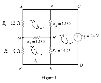
Ch. 2 - Find I1 in the circuit in Fig.P2.11.Ch. 2 - Find I0 and I1 in the circuit in Fig.P2.12.Ch. 2 - Find Ix,Iy, and Iz in the network in Fig.P2.13.Ch. 2 - Find Ix in the circuit in Fig.P2.14.Ch. 2 - Find Ix in the network in Fig. P2.15.Ch. 2 - Find I1 in the network in Fig. P2.16.Ch. 2 - Find Vbd in the circuit in Fig. P2.17.Ch. 2 - Find I1 in the circuit in Fig. P2.18.Ch. 2 - Find I1,I2, and I3 in the network in Fig. P2.19.Ch. 2 - Find Vfb and Vec in the circuit in Fig. P2.20.Ch. 2 - Given the circuit diagram in Fig. P2.21, find the...Ch. 2 - Find VBE and VDA in the circuit in Fig. P2.22.Ch. 2 - Find Vx and Vy in the circuit in Fig. P2.23.Ch. 2 - Find Vac in the circuit in Fig. P2.24.Ch. 2 - Find Vad and Vce in the circuit in Fig. P2.25.Ch. 2 - Find Vo in the circuit in Fig. P2.26.Ch. 2 - Find V1,V2, and V3 in the network in Fig. P2.27.Ch. 2 - Find Vo in the network in Fig. P2.28.Ch. 2 - Find V1,V2, and V3 in the network in Fig. P2.29.Ch. 2 - If Vo=3V in the circuit in Fig. P2.30, find Vs.Ch. 2 - Find the power supplied by each source in the...Ch. 2 - The 10-V source absorbs 2.5-mW of power. Calculate...Ch. 2 - Find Vbd in the network in Fig. P2.33.Ch. 2 - Find V1 in the network in Fig. P2.34.Ch. 2 - Find the power absorbed by the dependent source in...Ch. 2 - In the network in Fig. P2.36, find Vx,VAE, and VBD...Ch. 2 - In the network in Fig. P2.37, find VS if VEB=6V.Ch. 2 - Find VS in the circuit in Fig. P2.38, if VBE=18V.Ch. 2 - Find VA in the network in Fig. P2.39.Ch. 2 - If the 12-V source in the network in Fig. P2.40...Ch. 2 - If VX=12V in the network in Fig. P2.41, find VS...Ch. 2 - Calculate the power absorbed by the dependent...Ch. 2 - Find VA and VO in the circuit in Fig. P2.43.Ch. 2 - Find VO and the power absorbed by the 2k resistor...Ch. 2 - Find the power absorbed or supplied by the 12-V...Ch. 2 - Find Vo in the circuit in Fig. P2.46.Ch. 2 - Find I0 in the network in Fig. P2.47.Ch. 2 - Find Io in the network in Fig. P2.48.Ch. 2 - Find the power supplied by each source in the...Ch. 2 - Find the current IA in the circuit in Fig. P2.50.Ch. 2 - Find IS in the network in Fig. P2.51.Ch. 2 - Find Io in the circuit in Fig. P2.52.Ch. 2 - Find Io in the network in Fig. P2.53.Ch. 2 - Find Vo in the circuit in Fig. P2.54.Ch. 2 - Find Vo in the network in Fig. P2.55.Ch. 2 - Find Io in the network in Fig. P2.56.Ch. 2 - Find Io in the network in Fig. P2.57.Ch. 2 - Find IL in the circuit in Fig. P2.58.Ch. 2 - Find RAB in the network in Fig. P2.59.Ch. 2 - Find RAB in the circuit in Fig. P2.60.Ch. 2 - Find RAB in the circuit in Fig. P2.61.Ch. 2 - Find RAB in the network in Fig. P2.62.Ch. 2 - Find RAB in the circuit in Fig. P2.63.Ch. 2 - Find RAB in the circuit in Fig. P2.64.Ch. 2 - Find RAB in the circuit in Fig. P2.65.Ch. 2 - Find the equivalent resistance Req in the network...Ch. 2 - Find RAB in the network in Fig. P2.67.Ch. 2 - Given the resistor configuration shown in Fig....Ch. 2 - Determine the total resistance, RT, in the circuit...Ch. 2 - Determine the total resistance, RT, in the circuit...Ch. 2 - Determine the total resistance, RT, in the circuit...Ch. 2 - Find the power supplied by the source in the...Ch. 2 - Find I1 and Vo in the circuit in Fig. P2.73.Ch. 2 - Find I1 and Vo in the circuit in Fig. P2.74.Ch. 2 - Find Vab and Vdc in the circuit in Fig. P2.75.Ch. 2 - Find Io in the network in Fig. P2.76.Ch. 2 - Find Io in the circuit in Fig. P2.77.Ch. 2 - Find V1 in the network in Fig. P2.78.Ch. 2 - Find Vab in the circuit in Fig. P2.79.Ch. 2 - Find Vab in the network in Fig. P2.80.Ch. 2 - Find I1,I2, and V1 in the circuit in Fig. P2.81.Ch. 2 - Determine Vo in the network in Fig. P2.82.Ch. 2 - Calculate VAB in Fig. P2.83.Ch. 2 - Find Io in the network in Fig. P2.84 if all...Ch. 2 - Find Io in the circuit in Fig. P2.85.Ch. 2 - Determine the power supplied by the 36-V source in...Ch. 2 - Find the power supplied by the current source in...Ch. 2 - In the network in Fig. P2.88, V1=12V. Find VS.Ch. 2 - In the circuit in Fig. P2.89, Vo=2V. Find IS.Ch. 2 - In the network in Fig. P2.90, V1=14V. Find VS.Ch. 2 - If VR=15V, find VX in Fig. P2.91.Ch. 2 - Find the value of IA in the network in Fig. P2.92.Ch. 2 - If V1=5V in the circuit in Fig. P2.93, find IS.Ch. 2 - Given that Vo=4V in the network in Fig. P2.94,...Ch. 2 - Find the value of VS in the network in Fig. P2.95...Ch. 2 - In the network in Fig. P2.96, VO=6V. Find IS.Ch. 2 - Find the value of V1 in the network in Fig. P2.97...Ch. 2 - Find the value of IA in the circuit in Fig. P2.98.Ch. 2 - If the power supplied by the 2-A current source is...Ch. 2 - The 40-V source in the circuit in Fig. P2.100 is...Ch. 2 - Find the value of the current source IA in the...Ch. 2 - Given Io=2mA in the network in Fig. P2.102, find...Ch. 2 - Find the value of Vx in the network in Fig....Ch. 2 - Given Ia=2mA in the circuit in Fig. P2.104, find...Ch. 2 - Given Va in the network in Fig. 2.105, find IA.Ch. 2 - Find the value of Vx in the circuit in Fig. P2.106...Ch. 2 - Find the power absorbed by the network in Fig....Ch. 2 - Find the value of g in the network in Fig. P2.108...Ch. 2 - Find the power supplied by the 24-V source in the...Ch. 2 - Find Io in circuit in Fig. P2.110.Ch. 2 - Find Io in circuit in Fig. P2.111.Ch. 2 - Determine the value of Vo in the network in Fig....Ch. 2 - If Vo in the circuit in Fig. P2.113 is 24 V, find...Ch. 2 - Find the value of VS in the network in Fig....Ch. 2 - Find the power supplied by the 6-mA source in the...Ch. 2 - Find Vo in the circuit in Fig. P2.116.Ch. 2 - Find Vo in the network in Fig. P2.117.Ch. 2 - Find I1 in the network in Fig. P2.118.Ch. 2 - A single-stage transistor amplifier is modeled as...Ch. 2 - Find Io in the circuit in Fig. P2.120.Ch. 2 - Find Vo in the circuit in Fig. P2.121.Ch. 2 - A typical transistor amplifier is shown in Fig....Ch. 2 - Find VX in the network in Fig. P2.123.Ch. 2 - Find Vo in the network in Fig. P2.124.Ch. 2 - Find I1,I2, and I3 in the circuit in Fig. P2.125.Ch. 2 - Find Io in the network in Fig. P2.126.Ch. 2 - Find the power absorbed by the 12-k resistor on...Ch. 2 - Find the power absorbed by the 12-k resistor in...Ch. 2 - Find the value of k in the network in Fig. P2.129...Ch. 2 - If the power absorbed by the 10-V source in Fig....Ch. 2 - If the power supplied by the 2-A current source in...Ch. 2 - What is the power generated by the source in the...Ch. 2 - Find v ah in the circuit in Fig. 2PFE-2. a. 5V c....Ch. 2 - If Req=10.8 in the circuit in Fig. 2PFE-3, what is...Ch. 2 - Find the equivalent resistance of the circuit in...Ch. 2 - The 100-V source is absorbing 50W of power in the...Ch. 2 - Find the power supplied by the 40-V source in the...Ch. 2 - What is the current I0 in the circuit in Fig....Ch. 2 - Find the voltage Vo in the network in Fig. 2PFE-8....Ch. 2 - What is the voltage Vo in the circuit in Fig....Ch. 2 - Find the current Ix in Fig. 2PFE-10. a. 1/2Ac....
Additional Engineering Textbook Solutions
Find more solutions based on key concepts
7.13* For a bearing
DE = NUS 5 53’56 ”WT and angles to the right, compute the bearing of PG if angle
DEF 2 88°...
Elementary Surveying: An Introduction To Geomatics (15th Edition)
What is denormalization?
Database Concepts (8th Edition)
If = 75, determine the magnitudes of F and Fy. Probs. 2-84/85
INTERNATIONAL EDITION---Engineering Mechanics: Statics, 14th edition (SI unit)
Why were computer programming languages invented?
Starting Out With Visual Basic (8th Edition)
Does the Do-While loop test its condition before or after it performs an iteration?
Starting Out with Programming Logic and Design (5th Edition) (What's New in Computer Science)
The ____________ is always transparent.
Web Development and Design Foundations with HTML5 (8th Edition)
Knowledge Booster


Learn more about
Need a deep-dive on the concept behind this application? Look no further. Learn more about this topic, electrical-engineering and related others by exploring similar questions and additional content below.Similar questions
- Questions: Q1: Verify that the average power generated equals the average power absorbed using the simulated values in Table 7-2. Q2: Verify that the reactive power generated equals the reactive power absorbed using the simulated values in Table 7-2. Q3: Why it is important to correct the power factor of a load? Q4: Find the ideal value of the capacitor theoretically that will result in unity power factor. Vs pp (V) VRIPP (V) VRLC PP (V) AT (μs) T (us) 8° pf Simulated 14 8.523 7.84 84.850 1000 29.88 0.866 Measured 14 8.523 7.854 82.94 1000 29.85 0.86733 Table 7-2 Power Calculations Pvs (mW) Qvs (mVAR) PRI (MW) Pay (mW) Qt (mVAR) Qc (mYAR) Simulated -12.93 -7.428 9.081 3.855 12.27 -4.84 Calculated -12.936 -7.434 9.083 3.856 12.32 -4.85 Part II: Power Factor Correction Table 7-3 Power Factor Correction AT (us) 0° pf Simulated 0 0 1 Measured 0 0 1arrow_forwardQuestions: Q1: Verify that the average power generated equals the average power absorbed using the simulated values in Table 7-2. Q2: Verify that the reactive power generated equals the reactive power absorbed using the simulated values in Table 7-2. Q3: Why it is important to correct the power factor of a load? Q4: Find the ideal value of the capacitor theoretically that will result in unity power factor. Vs pp (V) VRIPP (V) VRLC PP (V) AT (μs) T (us) 8° pf Simulated 14 8.523 7.84 84.850 1000 29.88 0.866 Measured 14 8.523 7.854 82.94 1000 29.85 0.86733 Table 7-2 Power Calculations Pvs (mW) Qvs (mVAR) PRI (MW) Pay (mW) Qt (mVAR) Qc (mYAR) Simulated -12.93 -7.428 9.081 3.855 12.27 -4.84 Calculated -12.936 -7.434 9.083 3.856 12.32 -4.85 Part II: Power Factor Correction Table 7-3 Power Factor Correction AT (us) 0° pf Simulated 0 0 1 Measured 0 0 1arrow_forwardelectric plants. Prepare the load schedulearrow_forward
- electric plants Draw the column diagram. Calculate the voltage drop. by hand writingarrow_forwardelectric plants. Draw the lighting, socket, telephone, TV, and doorbell installations on the given single-story project with an architectural plan by hand writingarrow_forwardA circularly polarized wave, traveling in the +z-direction, is received by an elliptically polarized antenna whose reception characteristics near the main lobe are given approx- imately by E„ = [2â, + jâ‚]ƒ(r. 8, 4) Find the polarization loss factor PLF (dimensionless and in dB) when the incident wave is (a) right-hand (CW) An elliptically polarized wave traveling in the negative z-direction is received by a circularly polarized antenna. The vector describing the polarization of the incident wave is given by Ei= 2ax + jay.Find the polarization loss factor PLF (dimensionless and in dB) when the wave that would be transmitted by the antenna is (a) right-hand CParrow_forward
- jX(1)=j0.2p.u. jXa(2)=j0.15p.u. jxa(0)=0.15 p.u. V₁=1/0°p.u. V₂=1/0° p.u. 1 jXr(1) = j0.15 p.11. jXT(2) = j0.15 p.u. jXr(0) = j0.15 p.u. V3=1/0° p.u. А V4=1/0° p.u. 2 jX1(1)=j0.12 p.u. 3 jX2(1)=j0.15 p.u. 4 jX1(2)=0.12 p.11. JX1(0)=0.3 p.u. jX/2(2)=j0.15 p.11. X2(0)=/0.25 p.1. Figure 1. Circuit for Q3 b).arrow_forwardcan you show me full workings for this problem. the solution is - v0 = 10i2 = 2.941 volts, i0 = i1 – i2 = (5/3)i2 = 490.2mA.arrow_forwardQ4. a) Consider a transmission line modelled as a four-terminal network with an unknown configuration. You are provided with the following measured parameters at the operating frequency: Open-circuit voltage ratio: 0.9521° • Short-circuit impedance: 40+j80 • Open-circuit admittance: -j2 × 10-4 S Use the four terminal equations and the provided measurements to mathematically derive the A, B, C, and D parameters of the network and explain their physical significance. Show your work and formulas used in the derivation.arrow_forward
- Q1. Consider a single-phase step-down transformer with primary and secondary turns of 600 and 100 respectively and a primary voltage of 11 kV. (i) An open circuit test was conducted on the transformer and the primary current was measured as: I₁ = 2.20 A Use these results to calculate the magnetising reactance in the equivalent circuit (X) given that Rm, representing the core loss, has a value of 21 km. (ii) The remaining equivalent circuit parameters are as follows: R₁ = 40, X₁ = 25 N, R₂ = 0.4 N, X₂ = 0.3 N Draw the complete simplified equivalent circuit, by referring series components on the primary side to the secondary, giving all component values. (iii) The transformer is connected, on its secondary side, to a load of 10 at a power factor of 1. Calculate the voltage across the load. (iv) Calculate the efficiency of the transformer when operating at the load given in part (iii).arrow_forwardb) A 132 kV supply feeds a line of reactance 15 which is connected to a 100 MVA, 132/33 kV transformer of 0.08 p.u. reactance as shown in the Figure 2. The transformer feeds a 33 kV line of reactance 8 Q, which, in turn, is connected to a 75 MVA, 33/11 KV transformer of 0.12 p.u. reactance. The transformer supplies an 11 KV substation from which a local 11 kV feeder of 4 Q reactance is supplied. T1 T2 132 kV 33 kV 11 kV Fault X CB Relay Figure 2. Network for Q4 b). (i) Given the system base of 100 MVA, compute the total equivalent reactance of the radial circuit in per unit (p.u.). (ii) Determine the three-phase fault current at the load end of the 11 kV feeder, assuming a fault impedance of 0.05 Q. Calculate the fault current in Amperes. (iii) The 11 kV feeder connects to a protective overcurrent relay via 200/5 A current transformers. This relay has a standard normally inverse IDMT characteristic, with a setting current of 3 A and a time multiplier setting of 0.4. Calculate the…arrow_forwardQ2. a) Two three-phase transformers, designated A and B, have the following secondary equivalent circuit parameters per phase: R₁ = 0.002 Q, XA = 0.03 Q, RB = 0.004 Q, X = 0.012 Q Transformer A is 250 kVA and transformer B is 450 kVA. Calculate how they share a load of 650 KVA when connected in parallel (assume the voltage ratios are equal) b) A step-up transformer is being specified for the beginning of a 3-phase, 4 wire high voltage transmission line. Discuss your recommendation for the configuration of the transformer connections on both the primary and secondary side of the transformer. c) Define power system protection and describe its fundamental purpose. Discuss the following key concepts including discrimination, stability, speed of operation, sensitivity, and reliability in the context of the power system protection components and schemes.arrow_forward
arrow_back_ios
SEE MORE QUESTIONS
arrow_forward_ios
Recommended textbooks for you
 Introductory Circuit Analysis (13th Edition)Electrical EngineeringISBN:9780133923605Author:Robert L. BoylestadPublisher:PEARSON
 Delmar's Standard Textbook Of ElectricityElectrical EngineeringISBN:9781337900348Author:Stephen L. HermanPublisher:Cengage Learning
 Programmable Logic ControllersElectrical EngineeringISBN:9780073373843Author:Frank D. PetruzellaPublisher:McGraw-Hill Education
 Fundamentals of Electric CircuitsElectrical EngineeringISBN:9780078028229Author:Charles K Alexander, Matthew SadikuPublisher:McGraw-Hill Education
 Electric Circuits. (11th Edition)Electrical EngineeringISBN:9780134746968Author:James W. Nilsson, Susan RiedelPublisher:PEARSON
 Engineering ElectromagneticsElectrical EngineeringISBN:9780078028151Author:Hayt, William H. (william Hart), Jr, BUCK, John A.Publisher:Mcgraw-hill Education,
Introductory Circuit Analysis (13th Edition)
Electrical Engineering
ISBN:9780133923605
Author:Robert L. Boylestad
Publisher:PEARSON
Delmar's Standard Textbook Of Electricity
Electrical Engineering
ISBN:9781337900348
Author:Stephen L. Herman
Publisher:Cengage Learning
Programmable Logic Controllers
Electrical Engineering
ISBN:9780073373843
Author:Frank D. Petruzella
Publisher:McGraw-Hill Education
Fundamentals of Electric Circuits
Electrical Engineering
ISBN:9780078028229
Author:Charles K Alexander, Matthew Sadiku
Publisher:McGraw-Hill Education
Electric Circuits. (11th Edition)
Electrical Engineering
ISBN:9780134746968
Author:James W. Nilsson, Susan Riedel
Publisher:PEARSON
Engineering Electromagnetics
Electrical Engineering
ISBN:9780078028151
Author:Hayt, William H. (william Hart), Jr, BUCK, John A.
Publisher:Mcgraw-hill Education,
Current Divider Rule; Author: Neso Academy;https://www.youtube.com/watch?v=hRU1mKWUehY;License: Standard YouTube License, CC-BY