
Basic Engineering Circuit Analysis
11th Edition
ISBN: 9781118539293
Author: J. David Irwin, R. Mark Nelms
Publisher: WILEY
expand_more
expand_more
format_list_bulleted
Concept explainers
Videos
Textbook Question
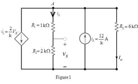
Chapter 2, Problem 52P
Find
Expert Solution & Answer
Want to see the full answer?
Check out a sample textbook solution
Students have asked these similar questions
A modulating signal f(t) is bandlimited to 5 kHz is sampled at a rate of 15000
samples/sec. The samples are quantized into 128 levels. Calculate the
transmission bandwidth if the following modulation types are used for signal
transmission:
4- ASK
5- 8-PSK
6- FSK with Af = 25 kHz
Draw the Split-Phase Manchester code for the follow ng binary data:
(1001010110)
11.54 For the network in Fig. 11.73, find the complex
power absorbed by each element.
120/-20° V
Figure 11.73
For Prob. 11.54.
| +
-1302
j5Q
4 Ω
Chapter 2 Solutions
Basic Engineering Circuit Analysis
Ch. 2 - Determine the current and power dissipated in the...Ch. 2 - Determine the voltage across the resistor in Fig....Ch. 2 - In the network in Fig. P2.3, the power absorbed by...Ch. 2 - In the network in Fig. P2.4, the power absorbed by...Ch. 2 - A model for a standard two D-cell flashlight is...Ch. 2 - An automobile uses two halogen headlights...Ch. 2 - Many years ago a string of Christmas tree lights...Ch. 2 - Find I1,I2, and I3 in the network in Fig.P2.8.Ch. 2 - Find I1 in the network in Fig.P2.9.Ch. 2 - Find I1 in the network in Fig.P2.10.
Ch. 2 - Find I1 in the circuit in Fig.P2.11.Ch. 2 - Find I0 and I1 in the circuit in Fig.P2.12.Ch. 2 - Find Ix,Iy, and Iz in the network in Fig.P2.13.Ch. 2 - Find Ix in the circuit in Fig.P2.14.Ch. 2 - Find Ix in the network in Fig. P2.15.Ch. 2 - Find I1 in the network in Fig. P2.16.Ch. 2 - Find Vbd in the circuit in Fig. P2.17.Ch. 2 - Find I1 in the circuit in Fig. P2.18.Ch. 2 - Find I1,I2, and I3 in the network in Fig. P2.19.Ch. 2 - Find Vfb and Vec in the circuit in Fig. P2.20.Ch. 2 - Given the circuit diagram in Fig. P2.21, find the...Ch. 2 - Find VBE and VDA in the circuit in Fig. P2.22.Ch. 2 - Find Vx and Vy in the circuit in Fig. P2.23.Ch. 2 - Find Vac in the circuit in Fig. P2.24.Ch. 2 - Find Vad and Vce in the circuit in Fig. P2.25.Ch. 2 - Find Vo in the circuit in Fig. P2.26.Ch. 2 - Find V1,V2, and V3 in the network in Fig. P2.27.Ch. 2 - Find Vo in the network in Fig. P2.28.Ch. 2 - Find V1,V2, and V3 in the network in Fig. P2.29.Ch. 2 - If Vo=3V in the circuit in Fig. P2.30, find Vs.Ch. 2 - Find the power supplied by each source in the...Ch. 2 - The 10-V source absorbs 2.5-mW of power. Calculate...Ch. 2 - Find Vbd in the network in Fig. P2.33.Ch. 2 - Find V1 in the network in Fig. P2.34.Ch. 2 - Find the power absorbed by the dependent source in...Ch. 2 - In the network in Fig. P2.36, find Vx,VAE, and VBD...Ch. 2 - In the network in Fig. P2.37, find VS if VEB=6V.Ch. 2 - Find VS in the circuit in Fig. P2.38, if VBE=18V.Ch. 2 - Find VA in the network in Fig. P2.39.Ch. 2 - If the 12-V source in the network in Fig. P2.40...Ch. 2 - If VX=12V in the network in Fig. P2.41, find VS...Ch. 2 - Calculate the power absorbed by the dependent...Ch. 2 - Find VA and VO in the circuit in Fig. P2.43.Ch. 2 - Find VO and the power absorbed by the 2k resistor...Ch. 2 - Find the power absorbed or supplied by the 12-V...Ch. 2 - Find Vo in the circuit in Fig. P2.46.Ch. 2 - Find I0 in the network in Fig. P2.47.Ch. 2 - Find Io in the network in Fig. P2.48.Ch. 2 - Find the power supplied by each source in the...Ch. 2 - Find the current IA in the circuit in Fig. P2.50.Ch. 2 - Find IS in the network in Fig. P2.51.Ch. 2 - Find Io in the circuit in Fig. P2.52.Ch. 2 - Find Io in the network in Fig. P2.53.Ch. 2 - Find Vo in the circuit in Fig. P2.54.Ch. 2 - Find Vo in the network in Fig. P2.55.Ch. 2 - Find Io in the network in Fig. P2.56.Ch. 2 - Find Io in the network in Fig. P2.57.Ch. 2 - Find IL in the circuit in Fig. P2.58.Ch. 2 - Find RAB in the network in Fig. P2.59.Ch. 2 - Find RAB in the circuit in Fig. P2.60.Ch. 2 - Find RAB in the circuit in Fig. P2.61.Ch. 2 - Find RAB in the network in Fig. P2.62.Ch. 2 - Find RAB in the circuit in Fig. P2.63.Ch. 2 - Find RAB in the circuit in Fig. P2.64.Ch. 2 - Find RAB in the circuit in Fig. P2.65.Ch. 2 - Find the equivalent resistance Req in the network...Ch. 2 - Find RAB in the network in Fig. P2.67.Ch. 2 - Given the resistor configuration shown in Fig....Ch. 2 - Determine the total resistance, RT, in the circuit...Ch. 2 - Determine the total resistance, RT, in the circuit...Ch. 2 - Determine the total resistance, RT, in the circuit...Ch. 2 - Find the power supplied by the source in the...Ch. 2 - Find I1 and Vo in the circuit in Fig. P2.73.Ch. 2 - Find I1 and Vo in the circuit in Fig. P2.74.Ch. 2 - Find Vab and Vdc in the circuit in Fig. P2.75.Ch. 2 - Find Io in the network in Fig. P2.76.Ch. 2 - Find Io in the circuit in Fig. P2.77.Ch. 2 - Find V1 in the network in Fig. P2.78.Ch. 2 - Find Vab in the circuit in Fig. P2.79.Ch. 2 - Find Vab in the network in Fig. P2.80.Ch. 2 - Find I1,I2, and V1 in the circuit in Fig. P2.81.Ch. 2 - Determine Vo in the network in Fig. P2.82.Ch. 2 - Calculate VAB in Fig. P2.83.Ch. 2 - Find Io in the network in Fig. P2.84 if all...Ch. 2 - Find Io in the circuit in Fig. P2.85.Ch. 2 - Determine the power supplied by the 36-V source in...Ch. 2 - Find the power supplied by the current source in...Ch. 2 - In the network in Fig. P2.88, V1=12V. Find VS.Ch. 2 - In the circuit in Fig. P2.89, Vo=2V. Find IS.Ch. 2 - In the network in Fig. P2.90, V1=14V. Find VS.Ch. 2 - If VR=15V, find VX in Fig. P2.91.Ch. 2 - Find the value of IA in the network in Fig. P2.92.Ch. 2 - If V1=5V in the circuit in Fig. P2.93, find IS.Ch. 2 - Given that Vo=4V in the network in Fig. P2.94,...Ch. 2 - Find the value of VS in the network in Fig. P2.95...Ch. 2 - In the network in Fig. P2.96, VO=6V. Find IS.Ch. 2 - Find the value of V1 in the network in Fig. P2.97...Ch. 2 - Find the value of IA in the circuit in Fig. P2.98.Ch. 2 - If the power supplied by the 2-A current source is...Ch. 2 - The 40-V source in the circuit in Fig. P2.100 is...Ch. 2 - Find the value of the current source IA in the...Ch. 2 - Given Io=2mA in the network in Fig. P2.102, find...Ch. 2 - Find the value of Vx in the network in Fig....Ch. 2 - Given Ia=2mA in the circuit in Fig. P2.104, find...Ch. 2 - Given Va in the network in Fig. 2.105, find IA.Ch. 2 - Find the value of Vx in the circuit in Fig. P2.106...Ch. 2 - Find the power absorbed by the network in Fig....Ch. 2 - Find the value of g in the network in Fig. P2.108...Ch. 2 - Find the power supplied by the 24-V source in the...Ch. 2 - Find Io in circuit in Fig. P2.110.Ch. 2 - Find Io in circuit in Fig. P2.111.Ch. 2 - Determine the value of Vo in the network in Fig....Ch. 2 - If Vo in the circuit in Fig. P2.113 is 24 V, find...Ch. 2 - Find the value of VS in the network in Fig....Ch. 2 - Find the power supplied by the 6-mA source in the...Ch. 2 - Find Vo in the circuit in Fig. P2.116.Ch. 2 - Find Vo in the network in Fig. P2.117.Ch. 2 - Find I1 in the network in Fig. P2.118.Ch. 2 - A single-stage transistor amplifier is modeled as...Ch. 2 - Find Io in the circuit in Fig. P2.120.Ch. 2 - Find Vo in the circuit in Fig. P2.121.Ch. 2 - A typical transistor amplifier is shown in Fig....Ch. 2 - Find VX in the network in Fig. P2.123.Ch. 2 - Find Vo in the network in Fig. P2.124.Ch. 2 - Find I1,I2, and I3 in the circuit in Fig. P2.125.Ch. 2 - Find Io in the network in Fig. P2.126.Ch. 2 - Find the power absorbed by the 12-k resistor on...Ch. 2 - Find the power absorbed by the 12-k resistor in...Ch. 2 - Find the value of k in the network in Fig. P2.129...Ch. 2 - If the power absorbed by the 10-V source in Fig....Ch. 2 - If the power supplied by the 2-A current source in...Ch. 2 - What is the power generated by the source in the...Ch. 2 - Find v ah in the circuit in Fig. 2PFE-2. a. 5V c....Ch. 2 - If Req=10.8 in the circuit in Fig. 2PFE-3, what is...Ch. 2 - Find the equivalent resistance of the circuit in...Ch. 2 - The 100-V source is absorbing 50W of power in the...Ch. 2 - Find the power supplied by the 40-V source in the...Ch. 2 - What is the current I0 in the circuit in Fig....Ch. 2 - Find the voltage Vo in the network in Fig. 2PFE-8....Ch. 2 - What is the voltage Vo in the circuit in Fig....Ch. 2 - Find the current Ix in Fig. 2PFE-10. a. 1/2Ac....
Additional Engineering Textbook Solutions
Find more solutions based on key concepts
In what year was Plankalkl designed? In what year was that design published?
Concepts Of Programming Languages
Why is it necessary to adjust the initial room-temperature clearance of a joint between two significantly dissi...
Degarmo's Materials And Processes In Manufacturing
The __________ mode flag causes an offset to be calculated from the beginning of a file.
Starting Out with C++ from Control Structures to Objects (9th Edition)
Polymorphism allows you to write methods in a subclass that have the same name as methods in the superclass.
Starting Out with Python (4th Edition)
Give an example of each of the following, other than those described in this chapter, and clearly explain why y...
Modern Database Management
(Instance Variables) Explain the purpose of an instance variable.
Java How to Program, Early Objects (11th Edition) (Deitel: How to Program)
Knowledge Booster


Learn more about
Need a deep-dive on the concept behind this application? Look no further. Learn more about this topic, electrical-engineering and related others by exploring similar questions and additional content below.Similar questions
- Find a value of RL that can be connected to terminals a-b for maximum power transfer. Then, calculate maximum power that can be delivered to load RL.arrow_forwardA modulating signal f(t) is bandlimited to 5 kHz is sampled at a rate of 15000 samples/sec. The samples are quantized into 128 levels. Calculate the transmission bandwidth if the following modulation types are used for signal transmission: 4- ASK 5- 8-PSK 6- FSK with Af = 25 kHzarrow_forwardA modulating signal f(t) is bandlimited to 5 kHz is sampled at a rate of 15000 samples/sec. The samples are quantized into 128 levels. Calculate the transmission bandwidth if the following modulation types are used for signal transmission: 4- ASK 5- 8-PSK 6- FSK with Af = 25 kHzarrow_forward
- Don't use ai to answer I will report you answerarrow_forwardjan G(f) f Sketch the spectrum of g(t), which has a maximum frequency of 5 kHz, if it is sampled at the following sampling frequencies: 7 kHz, 10 kHz and 15 kHz. Indicate if and how the signal can be recovered at each sampling frequency.arrow_forwardDon't use ai to answer i will report your answerarrow_forward
- A single tone is modulated using FM transmitter. The SNR, at the input of the demodulator 20 dB. If the maximum frequency of the modulating signal is 4 kHz, and the maximum equency deviation is 12 kHz, find the SNR, and the bandwidth (using Carson rule) at the ollowing conditions: . For the given values of fm and Af. !. If the amplitude of the modulating signal is increased by 80%. 3. If the amplitude of the modulating signal is decreased by 50%, and frequency of modulating signal is increased by 50%.arrow_forwardThe circuit shown below on the left has the following parameters: V₁ = 5 V. R₁ = 40, R₂ = 40, α = 0.1. This circuit can be replaced by an equivalent circuit shown below on the right such that the voltage and current received by an arbitrary load resistor RL, are identical when connected to either circuits. Determine the value of the resistor R (in ) in the equivalent circuit. R₁ Rx R2 R₁ Vx R₁ Vi απ. barrow_forward1. Consider the following a unity feedback control system. R(s) + E(s) 500(s+2)(s+5)(s+6) s(s+8)(s+10)(s+12) -Y(s) Find the followings: a) Type of the system b) Static position error constant Kp, Static velocity error constant Ry and Static acceleration error constant Ka c) Find the steady-state error of the system for (i) step input 1(t), (ii) ramp input t 1(t), (iii) parabolic input t² 1(t). 2. Repeat the above problem for the following system. R(s) + E(s) 500(s + 2)(s + 5) (s+8)(s+ 10)(s+12) Y(s) 3. Repeat the above problem for the following system. R(s) + E(s) 500(s+2)(s+4)(s+5)(s+6)(s+7) s²(s+8)(s+10)(s+12) Y(s)arrow_forward
- 4. Consider a unity (negative) feedback control system whose open-loop transfer function is given by the following. 2 G(s) = s³ (s + 2) Find the steady-state error of the system for each of the following inputs. = a) u(t) (t²+8t+5) 1(t) b) u(t) = 3t³ 1(t) c) u(t) (t+5t² - 1) 1(t) =arrow_forward1 2. For the following closed-loop system, G(s) = and H(s) = ½ (s+4)(s+6) a. Please draw the root locus by hand and mark the root locus with arrows. Calculate the origin and angle for asymptotes. b. Use Matlab to draw the root locus to verify your sketch. Input R(s) Output C(s) KG(s) H(s)arrow_forward5. Consider following feedback system. R(s) + 100 S+4 +1 Find the steady-state error for (i) step input and (ii) ramp input.arrow_forward
arrow_back_ios
SEE MORE QUESTIONS
arrow_forward_ios
Recommended textbooks for you
 Introductory Circuit Analysis (13th Edition)Electrical EngineeringISBN:9780133923605Author:Robert L. BoylestadPublisher:PEARSON
 Delmar's Standard Textbook Of ElectricityElectrical EngineeringISBN:9781337900348Author:Stephen L. HermanPublisher:Cengage Learning
 Programmable Logic ControllersElectrical EngineeringISBN:9780073373843Author:Frank D. PetruzellaPublisher:McGraw-Hill Education
 Fundamentals of Electric CircuitsElectrical EngineeringISBN:9780078028229Author:Charles K Alexander, Matthew SadikuPublisher:McGraw-Hill Education
 Electric Circuits. (11th Edition)Electrical EngineeringISBN:9780134746968Author:James W. Nilsson, Susan RiedelPublisher:PEARSON
 Engineering ElectromagneticsElectrical EngineeringISBN:9780078028151Author:Hayt, William H. (william Hart), Jr, BUCK, John A.Publisher:Mcgraw-hill Education,
Introductory Circuit Analysis (13th Edition)
Electrical Engineering
ISBN:9780133923605
Author:Robert L. Boylestad
Publisher:PEARSON
Delmar's Standard Textbook Of Electricity
Electrical Engineering
ISBN:9781337900348
Author:Stephen L. Herman
Publisher:Cengage Learning
Programmable Logic Controllers
Electrical Engineering
ISBN:9780073373843
Author:Frank D. Petruzella
Publisher:McGraw-Hill Education
Fundamentals of Electric Circuits
Electrical Engineering
ISBN:9780078028229
Author:Charles K Alexander, Matthew Sadiku
Publisher:McGraw-Hill Education
Electric Circuits. (11th Edition)
Electrical Engineering
ISBN:9780134746968
Author:James W. Nilsson, Susan Riedel
Publisher:PEARSON
Engineering Electromagnetics
Electrical Engineering
ISBN:9780078028151
Author:Hayt, William H. (william Hart), Jr, BUCK, John A.
Publisher:Mcgraw-hill Education,
Current Divider Rule; Author: Neso Academy;https://www.youtube.com/watch?v=hRU1mKWUehY;License: Standard YouTube License, CC-BY