
Basic Engineering Circuit Analysis
11th Edition
ISBN: 9781118539293
Author: J. David Irwin, R. Mark Nelms
Publisher: WILEY
expand_more
expand_more
format_list_bulleted
Concept explainers
Videos
Textbook Question
Chapter 2, Problem 108P
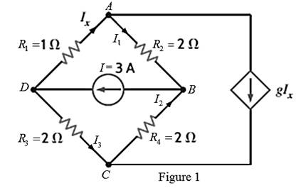
Find the value of g in the network in Fig. P2.108 such that the power supplied by the 3-A source is 20 W.
Expert Solution & Answer
Want to see the full answer?
Check out a sample textbook solution
Students have asked these similar questions
Example: Electric Field and Potential Inside a Charged Sphere
Problem: A sphere of radius R = 0.2 m is uniformly charged with a total charge Q = 5 μC. The sphere
is made of a dielectric material with relative permittivity € = 4. Calculate:
1. The electric field intensity E(r) inside and outside the sphere.
2. The electric potential (r) at any point inside the sphere.
Solution:
Step 1: Given Data
Radius of the sphere: R = 0.2m,
Total charge: Q-5 μC=5× 10° C.
Step 2: Electric Field Inside the Sphere (<
Using Gauss's Law:
please remember to draw the circuits
A balanced three-phase, A - connected induction motor consumes 3246 W when the l
voltage is 208 V, and the line current is 10.6 A. Calculate:
i. The motor's winding resistance.
ii.
The motor's winding reactance.
12 m
Chapter 2 Solutions
Basic Engineering Circuit Analysis
Ch. 2 - Determine the current and power dissipated in the...Ch. 2 - Determine the voltage across the resistor in Fig....Ch. 2 - In the network in Fig. P2.3, the power absorbed by...Ch. 2 - In the network in Fig. P2.4, the power absorbed by...Ch. 2 - A model for a standard two D-cell flashlight is...Ch. 2 - An automobile uses two halogen headlights...Ch. 2 - Many years ago a string of Christmas tree lights...Ch. 2 - Find I1,I2, and I3 in the network in Fig.P2.8.Ch. 2 - Find I1 in the network in Fig.P2.9.Ch. 2 - Find I1 in the network in Fig.P2.10.
Ch. 2 - Find I1 in the circuit in Fig.P2.11.Ch. 2 - Find I0 and I1 in the circuit in Fig.P2.12.Ch. 2 - Find Ix,Iy, and Iz in the network in Fig.P2.13.Ch. 2 - Find Ix in the circuit in Fig.P2.14.Ch. 2 - Find Ix in the network in Fig. P2.15.Ch. 2 - Find I1 in the network in Fig. P2.16.Ch. 2 - Find Vbd in the circuit in Fig. P2.17.Ch. 2 - Find I1 in the circuit in Fig. P2.18.Ch. 2 - Find I1,I2, and I3 in the network in Fig. P2.19.Ch. 2 - Find Vfb and Vec in the circuit in Fig. P2.20.Ch. 2 - Given the circuit diagram in Fig. P2.21, find the...Ch. 2 - Find VBE and VDA in the circuit in Fig. P2.22.Ch. 2 - Find Vx and Vy in the circuit in Fig. P2.23.Ch. 2 - Find Vac in the circuit in Fig. P2.24.Ch. 2 - Find Vad and Vce in the circuit in Fig. P2.25.Ch. 2 - Find Vo in the circuit in Fig. P2.26.Ch. 2 - Find V1,V2, and V3 in the network in Fig. P2.27.Ch. 2 - Find Vo in the network in Fig. P2.28.Ch. 2 - Find V1,V2, and V3 in the network in Fig. P2.29.Ch. 2 - If Vo=3V in the circuit in Fig. P2.30, find Vs.Ch. 2 - Find the power supplied by each source in the...Ch. 2 - The 10-V source absorbs 2.5-mW of power. Calculate...Ch. 2 - Find Vbd in the network in Fig. P2.33.Ch. 2 - Find V1 in the network in Fig. P2.34.Ch. 2 - Find the power absorbed by the dependent source in...Ch. 2 - In the network in Fig. P2.36, find Vx,VAE, and VBD...Ch. 2 - In the network in Fig. P2.37, find VS if VEB=6V.Ch. 2 - Find VS in the circuit in Fig. P2.38, if VBE=18V.Ch. 2 - Find VA in the network in Fig. P2.39.Ch. 2 - If the 12-V source in the network in Fig. P2.40...Ch. 2 - If VX=12V in the network in Fig. P2.41, find VS...Ch. 2 - Calculate the power absorbed by the dependent...Ch. 2 - Find VA and VO in the circuit in Fig. P2.43.Ch. 2 - Find VO and the power absorbed by the 2k resistor...Ch. 2 - Find the power absorbed or supplied by the 12-V...Ch. 2 - Find Vo in the circuit in Fig. P2.46.Ch. 2 - Find I0 in the network in Fig. P2.47.Ch. 2 - Find Io in the network in Fig. P2.48.Ch. 2 - Find the power supplied by each source in the...Ch. 2 - Find the current IA in the circuit in Fig. P2.50.Ch. 2 - Find IS in the network in Fig. P2.51.Ch. 2 - Find Io in the circuit in Fig. P2.52.Ch. 2 - Find Io in the network in Fig. P2.53.Ch. 2 - Find Vo in the circuit in Fig. P2.54.Ch. 2 - Find Vo in the network in Fig. P2.55.Ch. 2 - Find Io in the network in Fig. P2.56.Ch. 2 - Find Io in the network in Fig. P2.57.Ch. 2 - Find IL in the circuit in Fig. P2.58.Ch. 2 - Find RAB in the network in Fig. P2.59.Ch. 2 - Find RAB in the circuit in Fig. P2.60.Ch. 2 - Find RAB in the circuit in Fig. P2.61.Ch. 2 - Find RAB in the network in Fig. P2.62.Ch. 2 - Find RAB in the circuit in Fig. P2.63.Ch. 2 - Find RAB in the circuit in Fig. P2.64.Ch. 2 - Find RAB in the circuit in Fig. P2.65.Ch. 2 - Find the equivalent resistance Req in the network...Ch. 2 - Find RAB in the network in Fig. P2.67.Ch. 2 - Given the resistor configuration shown in Fig....Ch. 2 - Determine the total resistance, RT, in the circuit...Ch. 2 - Determine the total resistance, RT, in the circuit...Ch. 2 - Determine the total resistance, RT, in the circuit...Ch. 2 - Find the power supplied by the source in the...Ch. 2 - Find I1 and Vo in the circuit in Fig. P2.73.Ch. 2 - Find I1 and Vo in the circuit in Fig. P2.74.Ch. 2 - Find Vab and Vdc in the circuit in Fig. P2.75.Ch. 2 - Find Io in the network in Fig. P2.76.Ch. 2 - Find Io in the circuit in Fig. P2.77.Ch. 2 - Find V1 in the network in Fig. P2.78.Ch. 2 - Find Vab in the circuit in Fig. P2.79.Ch. 2 - Find Vab in the network in Fig. P2.80.Ch. 2 - Find I1,I2, and V1 in the circuit in Fig. P2.81.Ch. 2 - Determine Vo in the network in Fig. P2.82.Ch. 2 - Calculate VAB in Fig. P2.83.Ch. 2 - Find Io in the network in Fig. P2.84 if all...Ch. 2 - Find Io in the circuit in Fig. P2.85.Ch. 2 - Determine the power supplied by the 36-V source in...Ch. 2 - Find the power supplied by the current source in...Ch. 2 - In the network in Fig. P2.88, V1=12V. Find VS.Ch. 2 - In the circuit in Fig. P2.89, Vo=2V. Find IS.Ch. 2 - In the network in Fig. P2.90, V1=14V. Find VS.Ch. 2 - If VR=15V, find VX in Fig. P2.91.Ch. 2 - Find the value of IA in the network in Fig. P2.92.Ch. 2 - If V1=5V in the circuit in Fig. P2.93, find IS.Ch. 2 - Given that Vo=4V in the network in Fig. P2.94,...Ch. 2 - Find the value of VS in the network in Fig. P2.95...Ch. 2 - In the network in Fig. P2.96, VO=6V. Find IS.Ch. 2 - Find the value of V1 in the network in Fig. P2.97...Ch. 2 - Find the value of IA in the circuit in Fig. P2.98.Ch. 2 - If the power supplied by the 2-A current source is...Ch. 2 - The 40-V source in the circuit in Fig. P2.100 is...Ch. 2 - Find the value of the current source IA in the...Ch. 2 - Given Io=2mA in the network in Fig. P2.102, find...Ch. 2 - Find the value of Vx in the network in Fig....Ch. 2 - Given Ia=2mA in the circuit in Fig. P2.104, find...Ch. 2 - Given Va in the network in Fig. 2.105, find IA.Ch. 2 - Find the value of Vx in the circuit in Fig. P2.106...Ch. 2 - Find the power absorbed by the network in Fig....Ch. 2 - Find the value of g in the network in Fig. P2.108...Ch. 2 - Find the power supplied by the 24-V source in the...Ch. 2 - Find Io in circuit in Fig. P2.110.Ch. 2 - Find Io in circuit in Fig. P2.111.Ch. 2 - Determine the value of Vo in the network in Fig....Ch. 2 - If Vo in the circuit in Fig. P2.113 is 24 V, find...Ch. 2 - Find the value of VS in the network in Fig....Ch. 2 - Find the power supplied by the 6-mA source in the...Ch. 2 - Find Vo in the circuit in Fig. P2.116.Ch. 2 - Find Vo in the network in Fig. P2.117.Ch. 2 - Find I1 in the network in Fig. P2.118.Ch. 2 - A single-stage transistor amplifier is modeled as...Ch. 2 - Find Io in the circuit in Fig. P2.120.Ch. 2 - Find Vo in the circuit in Fig. P2.121.Ch. 2 - A typical transistor amplifier is shown in Fig....Ch. 2 - Find VX in the network in Fig. P2.123.Ch. 2 - Find Vo in the network in Fig. P2.124.Ch. 2 - Find I1,I2, and I3 in the circuit in Fig. P2.125.Ch. 2 - Find Io in the network in Fig. P2.126.Ch. 2 - Find the power absorbed by the 12-k resistor on...Ch. 2 - Find the power absorbed by the 12-k resistor in...Ch. 2 - Find the value of k in the network in Fig. P2.129...Ch. 2 - If the power absorbed by the 10-V source in Fig....Ch. 2 - If the power supplied by the 2-A current source in...Ch. 2 - What is the power generated by the source in the...Ch. 2 - Find v ah in the circuit in Fig. 2PFE-2. a. 5V c....Ch. 2 - If Req=10.8 in the circuit in Fig. 2PFE-3, what is...Ch. 2 - Find the equivalent resistance of the circuit in...Ch. 2 - The 100-V source is absorbing 50W of power in the...Ch. 2 - Find the power supplied by the 40-V source in the...Ch. 2 - What is the current I0 in the circuit in Fig....Ch. 2 - Find the voltage Vo in the network in Fig. 2PFE-8....Ch. 2 - What is the voltage Vo in the circuit in Fig....Ch. 2 - Find the current Ix in Fig. 2PFE-10. a. 1/2Ac....
Additional Engineering Textbook Solutions
Find more solutions based on key concepts
Determine the resultant internal normal force, shear force, and bending moment at point C in the beam.
Mechanics of Materials (10th Edition)
Describe the difference between the tellg and the tellp functions.
Starting Out with C++ from Control Structures to Objects (9th Edition)
Write assignment statements that perform the following operations with the variables a, b, and c. a. Adds 2 to ...
Starting Out with Java: From Control Structures through Objects (7th Edition) (What's New in Computer Science)
True or False: The superclass constructor always executes before the subclass constructor.
Starting Out with Java: From Control Structures through Data Structures (4th Edition) (What's New in Computer Science)
This statement can cause other program statements to execute only under certain conditions. 1. Conditional 2. D...
Starting Out With Visual Basic (8th Edition)
Lottery Number Generator Design a program that generates a 7-digit lottery number. The program should have an I...
Starting Out with Programming Logic and Design (5th Edition) (What's New in Computer Science)
Knowledge Booster


Learn more about
Need a deep-dive on the concept behind this application? Look no further. Learn more about this topic, electrical-engineering and related others by exploring similar questions and additional content below.Similar questions
- a) An iron ring, having a mean circumference of 250 mm and a cross-sectional area of 400 mm², is wound with a coil of 70 turns. Using the following data, calculate the current required to set up a flux of 510µWb in the ring. H (A/m) 350 600 1250 B (T) 1.0 1.2 1.4 b) Calculate also: i. The inductance of the coil at the current obtained in Question 2 (a) above. ii. The self-induced e.m.f. if this current is switched off in 0.005 s. Assume that there is no residual flux.arrow_forwardA balanced three-phase, 1351-V, 60-Hz, A-connected source feeds a balanced Y- connected load with a per-phase impedance of 360 + j150 Q as shown in Figure 1. Calculate: i. The readings on each of the wattmeters ii. The power factor of the load using the wattmeter readings. NOTE: i. ii. Let VAN be the reference phasor, and the phase sequence be ABC anticlockwise. Assume the voltage-drop on the conductors between the source and the load to be zero volts. V b V₁ W 000 000 ; A 360 + j150 360 + j150 4 b 0000 000 B 360 + j150 C W₂ Figure 1arrow_forwarda) Three 30 2 resistors are arranged as shown in Figure 1 below. They are connected to a 480 V three-phase supply. The phase sequence is RYB anticlockwise. Calculate: i. The total power drawn by the circuit using the phase parameters. ii. The power read by each wattmeter. b) If Za, one of the 30 2 resistors, is now removed from the circuit, calculate: R- i. The line currents: IR, Iv, and la ii. The power read by each wattmeter. iii. The total power drawn by the two resistors. W₁ Be- W2 www 'R 22 12 B Figure 1arrow_forward
- A certain magnetic circuit may be regarded as consisting of three parts, A, B and C in series, each one of which has a uniform cross-sectional area. Part A has a length of 300 mm and a cross- sectional area of 450 mm². Part B has a length of 120 mm and a cross-sectional area of 300 mm². Part C is an airgap 1.0 mm in length and of cross-sectional area 350 mm². The flux in the airgap is 0.35 mWb. Neglect magnetic leakage and fringing. The magnetic characteristic for parts A and B is given by: H (A/m) 400 560 800 1280 1800 B (T) 0.7 0.85 1.0 1.15 1.25 Calculate: i. The reluctance of each part, that is, of Part A, Part B, and Part C ii. The total reluctance of the magnetic circuit. iii. The total m.m.f.arrow_forwardHW_02.pdf EE 213-01 Assignments HW_#2 Toms are as muIcate uah.instructure.com b Answered: HW_#1 HW_01.pdf EE 213-01 Assignments P Pearson MyLab and Mastering uah.instructure.com P Course Home Watc... ✓ Download → Info × Close 1) (5 pts)For the circuit shown, find the value of Ia, Ib, Ic and Va: Ib 10 Ohms + Ic 40 Ohms 20 Ohms 70 Volts a Page 1 > of 2 - ZOOM + pui via Canvas Hint: use KCL to find Ic in terms of la and lb, use KVL around the right loop to find a relationship between la and lb, use KVL around the outer loop to solve for a current value (use ohms law for the voltage drops across the resistors) 2) (5 pts) – For problem 1, show that the power supplied (delivered) by the source equals the power absorbed by the resistors. 3) (5 pts) Determine the equivalent resistance looking into terminals a-b for the two circuits shown. Use series and parallel resistor combinations. Hint: work from the opposite end of terminals a-b towards terminals a-b a) 24 Ohms 10 Ohms 8 Ohms G a REQ b)…arrow_forwardA three-phase load consists of three identical impedances connected in delta. The impedances have a value of (100 + j40) Q. The supply voltage is 440 V. The two- wattmeter method is used to determine the total power drawn by the load. One wattmeter, W₁, has its current coil connected in the blue line and its voltage coil connected between the yellow and blue lines. Calculate: a) The power measured by each wattmeter b) The power factor of the load using the wattmeter readings c) The apparent power supplied to the load d) The reactive power drawn by the load.arrow_forward
- 4- A 75 KW, 250 V shunt generator has R₁ = 0.03 2 and RF =50 2. The generator has 6 poles and is lap wound with totally 400 conductors. The generator runs at 600 rpm on full load. The bore of the machine is 42 cm (in diameter), its axial length is 28 cm and each pole subtends an angle of 54 °. Field pole a) b) c) Find the airgap flux density. (10 pt) Find the induced voltage under full load. (10 pt) Find the average number of active conductors. (5 pts) 28 cm 21 cm 60° Armaturearrow_forwarda) The phase currents in a delta - connected three-phase load are as follows: between the red and yellow lines, 60 A at p.f. 0.9 leading; between the yellow and blue lines, 40 A at 0.95 p.f lagging; between the blue and red lines, 50 A at p.f. 0.8 lagging. The supply voltage is 240 V. Draw a labeled diagram of the circuit and calculate the line currents. Note: Use VRY as the reference phasor. b) The two-wattmeter method is used to measure the total power drawn by the load in 1 (a) above. Wattmeter one has its current coil connected in the yellow line and its voltage coil connected between the yellow and red lines. Calculate: i. The power measured by each wattmeter. ii. The power factor of the load.arrow_forwardQUESTION NO. 1 a) State Lenz Law b) Explain Flux density c) A wire, 100 mm long, is moved at a uniform speed of 4 m/s at right angles to its length and to a uniform magnetic field. Calculate the density of the field if the e.m.f. generated in the wire is 0.15 V. If the wire forms part of a closed circuit having a total resistance of 0.04 2, calculate the force on the wire in newtons.arrow_forward
- In Figure (a) the drawing of the bipolar circuit was as shown in Figure 4. Draw me a unipolar circuit and how it will be in Figure (b). Please draw the circuit with the transistors.arrow_forwardSOLVE ON PAPER NOT BY CHATGPTarrow_forwardDraw fabrication layer transistor MS (schottky diode)arrow_forward
arrow_back_ios
SEE MORE QUESTIONS
arrow_forward_ios
Recommended textbooks for you
 Introductory Circuit Analysis (13th Edition)Electrical EngineeringISBN:9780133923605Author:Robert L. BoylestadPublisher:PEARSON
 Delmar's Standard Textbook Of ElectricityElectrical EngineeringISBN:9781337900348Author:Stephen L. HermanPublisher:Cengage Learning
 Programmable Logic ControllersElectrical EngineeringISBN:9780073373843Author:Frank D. PetruzellaPublisher:McGraw-Hill Education
 Fundamentals of Electric CircuitsElectrical EngineeringISBN:9780078028229Author:Charles K Alexander, Matthew SadikuPublisher:McGraw-Hill Education
 Electric Circuits. (11th Edition)Electrical EngineeringISBN:9780134746968Author:James W. Nilsson, Susan RiedelPublisher:PEARSON
 Engineering ElectromagneticsElectrical EngineeringISBN:9780078028151Author:Hayt, William H. (william Hart), Jr, BUCK, John A.Publisher:Mcgraw-hill Education,
Introductory Circuit Analysis (13th Edition)
Electrical Engineering
ISBN:9780133923605
Author:Robert L. Boylestad
Publisher:PEARSON
Delmar's Standard Textbook Of Electricity
Electrical Engineering
ISBN:9781337900348
Author:Stephen L. Herman
Publisher:Cengage Learning
Programmable Logic Controllers
Electrical Engineering
ISBN:9780073373843
Author:Frank D. Petruzella
Publisher:McGraw-Hill Education
Fundamentals of Electric Circuits
Electrical Engineering
ISBN:9780078028229
Author:Charles K Alexander, Matthew Sadiku
Publisher:McGraw-Hill Education
Electric Circuits. (11th Edition)
Electrical Engineering
ISBN:9780134746968
Author:James W. Nilsson, Susan Riedel
Publisher:PEARSON
Engineering Electromagnetics
Electrical Engineering
ISBN:9780078028151
Author:Hayt, William H. (william Hart), Jr, BUCK, John A.
Publisher:Mcgraw-hill Education,
Current Divider Rule; Author: Neso Academy;https://www.youtube.com/watch?v=hRU1mKWUehY;License: Standard YouTube License, CC-BY