
EBK ELECTRICAL ENGINEERING
7th Edition
ISBN: 8220106714201
Author: HAMBLEY
Publisher: YUZU
expand_more
expand_more
format_list_bulleted
Concept explainers
Videos
Textbook Question
thumb_up100%
Chapter 2, Problem 2.82P
Find the Thévenin and Norton equivalent circuits for the circuit shown in Figure P2.82.
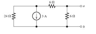
Figure P2.82
Expert Solution & Answer

Trending nowThis is a popular solution!

Learn your wayIncludes step-by-step video

schedule06:23
Students have asked these similar questions
not use ai please
In matlab
EXAMPLE 4.4
In a binary symmetric communication (BSC) channel, the input bits transmitted over the channel
are either 0 or 1 with probabilities p and 1-p, respectively. Due to channel noise, errors are made.
As shown in Figure 4.4, the channel is assumed to be symmetric, which means the probability of
receiving 1 when 0 is transmitted is the same as the probability of receiving 0 when 1 is transmit-
ted. The conditional probabilities of error are assumed to be each e. Determine the average prob-
ability of error, also known as the bit error rate, as well as the a posteriori probabilities.
Chapter 2 Solutions
EBK ELECTRICAL ENGINEERING
Ch. 2 - Reduce each of the networks shown in Figure P2.1...Ch. 2 - A 4- resistance is in series with the parallel...Ch. 2 - Find the equivalent resistance looking into...Ch. 2 - Suppose that we need a resistance of 1.5 k and...Ch. 2 - Find the equivalent resistance between terminals a...Ch. 2 - Find the equivalent resistance between terminals a...Ch. 2 - What resistance in parallel with 120 results in...Ch. 2 - Determine the resistance between terminals a and b...Ch. 2 - Two resistances having values of R and 2R are in...Ch. 2 - A network connected between terminals a and b...
Ch. 2 - Two resistances R1 and R2 are connected in...Ch. 2 - Find the equivalent resistance for the infinite...Ch. 2 - If we connect n 1000- resistances in parallel,...Ch. 2 - The heating element of an electric cook top has...Ch. 2 - We are designing an electric space heater to...Ch. 2 - Sometimes, we can use symmetry considerations to...Ch. 2 - The equivalent resistance between terminals a and...Ch. 2 - Three conductances G1 G2, and G3 are in series....Ch. 2 - Most sources of electrical power behave as...Ch. 2 - The resistance for the network shown in Figure...Ch. 2 - Often, we encounter delta-connected loads such as...Ch. 2 - What are the steps in solving a circuit by network...Ch. 2 - Find the values of i1 and i2 in Figure P2.23....Ch. 2 - Find the voltages v1 and v2 for the circuit shown...Ch. 2 - Find the values of v and i in Figure P2.25. Figure...Ch. 2 - Consider the circuit shown in Figure P2.24....Ch. 2 - Find the voltage v and the currents i1 and 12 for...Ch. 2 - Find the values of vs, v1, and i2 in Figure P2.28....Ch. 2 - Find the values of i1 and i2 in Figure P2.29....Ch. 2 - Consider the cirrcuit shown in Figure P2.30 Find...Ch. 2 - Solve for the values of i1, i2, and the powers for...Ch. 2 - The 12-V source in Figure P2.32 is delivering 36...Ch. 2 - Refer to the circuit shown in Figure P2.33. With...Ch. 2 - Find the values of i1 and i2 in Figure P2.34. Find...Ch. 2 - Find the values of i1 and i2 in Figure P2.35...Ch. 2 - Use the voltage-division principle to calculate...Ch. 2 - Use the current-division principle to calculate i1...Ch. 2 - Use the voltage-division principle to calculate...Ch. 2 - Use the current-division principle to calculate...Ch. 2 - Suppose we need to design a voltage-divider...Ch. 2 - A source supplies 120 V to the series combination...Ch. 2 - We have a 60- resistance, a 20- resistance, and...Ch. 2 - A worker is standing on a wet concrete floor,...Ch. 2 - Suppose we have a load that absorbs power and...Ch. 2 - We have a load resistance of 50 that we wish to...Ch. 2 - We have a load resistance of 1 k that we wish to...Ch. 2 - The circuit of Figure P2.47 is similar to networks...Ch. 2 - Write equations and solve for the node voltages...Ch. 2 - Solve for the node voltages shown in Figure P2.49....Ch. 2 - Solve for the node voltages shown in Figure P2.50....Ch. 2 - Given R1=4 , R2=5 , R2=8 , R4=10 , R5=2 , and...Ch. 2 - Determine the value of i1 in Figure P2.52 using...Ch. 2 - Given R1=15 , R5=5 , R3=20 , R4=10 , R5=8 , R6=4 ,...Ch. 2 - In solving a network, what rule must you observe...Ch. 2 - Use the symbolic features of MATLAB to find an...Ch. 2 - Solve for the values of the node voltages shown in...Ch. 2 - Solve for the node voltages shown in Figure P2.57....Ch. 2 - Solve for the power delivered to the 8- ...Ch. 2 - Solve for the node voltages shown in Figure P2.59....Ch. 2 - Find the equivalent resistance looking into...Ch. 2 - Find the equivalent resistance looking into...Ch. 2 - Figure P2.62 shows an unusual voltage-divider...Ch. 2 - Solve for the node voltages in the circuit of...Ch. 2 - We have a cube with 1- resistances along each...Ch. 2 - Solve for the power delivered to the 15- resistor...Ch. 2 - Determine the value of v2 and the power delivered...Ch. 2 - Use mesh-current analysis to find the value of i1...Ch. 2 - Solve for the power delivered by the voltage...Ch. 2 - Use mesh-current analysis to find the value of v...Ch. 2 - Use mesh-current analysis to find the value of i3...Ch. 2 - Use mesh-current analysis to find the values of i1...Ch. 2 - Find the power delivered by the source and the...Ch. 2 - Use mesh-current analysis to find the values of i1...Ch. 2 - Use mesh-current analysis to find the values of i1...Ch. 2 - The circuit shown in Figure P2.75 is the dc...Ch. 2 - Use MATLAB and mesh-current analysis to determine...Ch. 2 - Connect a 1-V voltage source across terminals a...Ch. 2 - Connect a 1-V voltage source across the terminals...Ch. 2 - Use MATLAB to solve for the mesh currents in...Ch. 2 - Find the Thévenin and Norton equivalent circuits...Ch. 2 - We can model a certain battery as a voltage source...Ch. 2 - Find the Thévenin and Norton equivalent circuits...Ch. 2 - Find the Thévenin and Norton equivalent circuits...Ch. 2 - Find the Thévenin arid Norton equivalent circuits...Ch. 2 - An automotive battery has an open-circuit voltage...Ch. 2 - A certain two-terminal circuit has an open-circuit...Ch. 2 - If we measure the voltage at the terminals of a...Ch. 2 - Find the Thévenin and Norton equivalent circuits...Ch. 2 - Find the maximum power that can be delivered to a...Ch. 2 - Find the maximum power that can be delivered to a...Ch. 2 - Figure P2.91 shows a resistive load RL connected...Ch. 2 - Starling from the Norton equivalent circuit with a...Ch. 2 - A battery can be modeled by a voltage source Vt in...Ch. 2 - Use superposition to find the current i in Figure...Ch. 2 - Solve for is in Figure P2.49 by using...Ch. 2 - Solve the circuit shown in Figure P2.48 by using...Ch. 2 - Solve for i1 in Figure P2.34 by using...Ch. 2 - Another method of solving the circuit of Figure...Ch. 2 - Use the method of Problem P2.98 for the circuit of...Ch. 2 - Solve for the actual value of i6 for the circuit...Ch. 2 - Device A shown in Figure P2.101 has v=3i2 for i 0...Ch. 2 - The Wheatstone bridge shown in Figure 2.66 is...Ch. 2 - The Wheatstone bridge shown in Figure 2.66has...Ch. 2 - In theory, any values can be used for R1 and R3 in...Ch. 2 - Derive expressions for the Thévenin voltage and...Ch. 2 - Derive Equation 2.93 for the bridge circuit of...Ch. 2 - Prob. 2.107PCh. 2 - Explain what would happen if, in wiring the bridge...Ch. 2 - Match each entry in Table T2.1(a) with the best...Ch. 2 - Consider the circuit of Figure T2.2 with vs=96V ,...Ch. 2 - Write MATLAB code to solve for the node voltages...Ch. 2 - Write a set of equations that can be used to solve...Ch. 2 - Determine the Thévenin and Norton equivalent...Ch. 2 - According to the superposition principle, what...Ch. 2 - Determine the equivalent resistance between...Ch. 2 - Transform the 2-A current source and 6- ...
Knowledge Booster


Learn more about
Need a deep-dive on the concept behind this application? Look no further. Learn more about this topic, electrical-engineering and related others by exploring similar questions and additional content below.Similar questions
- What is the bandwidth requirement in Hz for baseband binary transmission at 64 kbps, if the roll-off factor is 0.25?arrow_forwardEXAMPLE 6.4 Suppose the roll-off factor is 25% and the bandwidth of a baseband transmission system satisfying the Nyquist criterion is 30 kHz. Determine the bit rate. Solution 1+α 1arrow_forwardEXAMPLE 4.9 In a communication system, the noise level is modeled as a Gaussian random variable with m=0 and ² = 0.0001. Determine P(X > 0.01) and P(-0.04 ≤x≤ 0.05). 3arrow_forward
- Suppose the random variable X is uniformly distributed between 0 and 1 with probability 0.25, takes on the value of 1 with probability p, and is uniformly distributed between 1 and 2 with probability 0.5. Determine p as well as the pdf and cdf of the random variable Xarrow_forwardconstants: A (medium) single phase transmission line 100 km long has the following Resistance/km = 0.25 2; Susceptance/km = 14 × 10 siemen; Reactance/km = 0.8 Receiving end line voltage = 66,000 V Assuming that the total capacitance of the line is localised at the receiving end alone, determine (i) the sending end current (ii) the sending end voltage (iii) regulation and (iv) supply power factor. The line is delivering 15,000 kW at 0.8 power factor lagging. Draw the phasor diagram to illustrate your calculations.arrow_forwardFor the power system given below, the voltage at bus 2 is kept at 1.03 pu. The maximum power can be delivered by G2 is 35 MW. Obtain the load flow solution. Take the base power 100 MVA. V₁ = 1.0520 G₁ 0.02+j0.06 G2 V2=1.03 P2 = 35 MW 0.08+j0.24 SL2 20+j50 MVA SL3 60+j25 MVA 0.06+j0.018arrow_forward
- General Directions: Read the questions carefully and answer (3*10=30marks) 1. Design a summing amplifier by choosing appropriate values of resistors an so that the output is 5 times the sum of the input voltages. (you are free to use any number of inputs, the type of op-amp, any value of resistors) 2. Derive the equation for the closed loop gain of the inverting and non-inverting Amplifier using appropriate circuit diagrams. 3. Determine the values read by the measuring devices using appropriate formulae www Voc +8V R₁ 33 k Rc 2.2 k ww WWW Poc 200 R₁₂ RE 10 kn 1.0 knarrow_forward十 : + B 日 العنوان I need a detailed drawing with explanation ややハメPV+96252 4 Project Homework: Create a simulation for a tank when the flowrate inside and outside the tank must range between 0 and 10 lit/s: 1) The level should be controlled within a range between more than zero to 1000 lit. 2) An alarm must be launched when the level is out of range (less than 100 and more than 900 lit). 3) When the capacity reaches to the maximum the motor turns OFF. area=A Qout -20 solve in lab view X9.01 *175*1arrow_forwardProject Homework: Create a simulation for a tank when the flowrate inside and outside the tank must range between 0 and 10 lit/s: 1) The level should be controlled within a range between more than zero to 1000 lit. 2) An alarm must be launched when the level is out of range (less than 100 and more than 900 lit). 3) When the capacity reaches to the maximum the motor turns OFF. Qin h C Qout area=A solve in lab viewarrow_forward
- QUESTION [3] A no-load and short-circuit test should be conducted on a 220V/110V, 280VA transformer. a. Draw the circuit diagram for the no-load test and include all measurements that should be made. Also write down the maximum voltage that you should apply to the primary winding and estimate the current drawn from the supply. (5) b. Draw a circuit diagram for the short-circuit test and include all measurements that should be made. Also write down the maximum current that should be allowed to flow in the primary winding and estimated the primary voltage that will cause this value of the current to flow. (5)arrow_forwardOnly expert should solve it pleasearrow_forwardNeed handwritten solution pleasearrow_forward
arrow_back_ios
SEE MORE QUESTIONS
arrow_forward_ios
Recommended textbooks for you
 Introductory Circuit Analysis (13th Edition)Electrical EngineeringISBN:9780133923605Author:Robert L. BoylestadPublisher:PEARSON
 Delmar's Standard Textbook Of ElectricityElectrical EngineeringISBN:9781337900348Author:Stephen L. HermanPublisher:Cengage Learning
 Programmable Logic ControllersElectrical EngineeringISBN:9780073373843Author:Frank D. PetruzellaPublisher:McGraw-Hill Education
 Fundamentals of Electric CircuitsElectrical EngineeringISBN:9780078028229Author:Charles K Alexander, Matthew SadikuPublisher:McGraw-Hill Education
 Electric Circuits. (11th Edition)Electrical EngineeringISBN:9780134746968Author:James W. Nilsson, Susan RiedelPublisher:PEARSON
 Engineering ElectromagneticsElectrical EngineeringISBN:9780078028151Author:Hayt, William H. (william Hart), Jr, BUCK, John A.Publisher:Mcgraw-hill Education,
Introductory Circuit Analysis (13th Edition)
Electrical Engineering
ISBN:9780133923605
Author:Robert L. Boylestad
Publisher:PEARSON
Delmar's Standard Textbook Of Electricity
Electrical Engineering
ISBN:9781337900348
Author:Stephen L. Herman
Publisher:Cengage Learning
Programmable Logic Controllers
Electrical Engineering
ISBN:9780073373843
Author:Frank D. Petruzella
Publisher:McGraw-Hill Education
Fundamentals of Electric Circuits
Electrical Engineering
ISBN:9780078028229
Author:Charles K Alexander, Matthew Sadiku
Publisher:McGraw-Hill Education
Electric Circuits. (11th Edition)
Electrical Engineering
ISBN:9780134746968
Author:James W. Nilsson, Susan Riedel
Publisher:PEARSON
Engineering Electromagnetics
Electrical Engineering
ISBN:9780078028151
Author:Hayt, William H. (william Hart), Jr, BUCK, John A.
Publisher:Mcgraw-hill Education,
Current Divider Rule; Author: Neso Academy;https://www.youtube.com/watch?v=hRU1mKWUehY;License: Standard YouTube License, CC-BY