
EBK ELECTRICAL ENGINEERING
7th Edition
ISBN: 8220106714201
Author: HAMBLEY
Publisher: YUZU
expand_more
expand_more
format_list_bulleted
Concept explainers
Videos
Textbook Question
Chapter 2, Problem 2.37P
Use the current-division principle to calculate i1 and i2 in Figure P2.37.
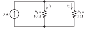
Figure P2.3
Expert Solution & Answer

Learn your wayIncludes step-by-step video

schedule02:52
Students have asked these similar questions
General Directions: Read the questions carefully and answer (3*10=30marks)
1. Design a summing amplifier by choosing appropriate values of resistors an so that
the output is 5 times the sum of the input voltages. (you are free to use any number
of inputs, the type of op-amp, any value of resistors)
2. Derive the equation for the closed loop gain of the inverting and non-inverting
Amplifier using appropriate circuit diagrams.
3. Determine the values read by the measuring devices using appropriate formulae
www
Voc
+8V
R₁
33 k
Rc
2.2 k
ww
WWW
Poc 200
R₁₂
RE
10 kn
1.0 kn
十
: + B
日
العنوان
I need a detailed drawing with explanation
ややハメPV+96252
4
Project Homework:
Create a simulation for a tank when the flowrate inside and outside the tank must
range between 0 and 10 lit/s:
1) The level should be controlled within a range between more than zero to 1000
lit.
2) An alarm must be launched when the level is out of range (less than 100 and
more than 900 lit).
3) When the capacity reaches to the maximum the motor turns OFF.
area=A
Qout
-20
solve in lab view
X9.01
*175*1
Project Homework:
Create a simulation for a tank when the flowrate inside and outside the tank must
range between 0 and 10 lit/s:
1) The level should be controlled within a range between more than zero to 1000
lit.
2) An alarm must be launched when the level is out of range (less than 100 and
more than 900 lit).
3) When the capacity reaches to the maximum the motor turns OFF.
Qin
h
C
Qout
area=A
solve in lab view
Chapter 2 Solutions
EBK ELECTRICAL ENGINEERING
Ch. 2 - Reduce each of the networks shown in Figure P2.1...Ch. 2 - A 4- resistance is in series with the parallel...Ch. 2 - Find the equivalent resistance looking into...Ch. 2 - Suppose that we need a resistance of 1.5 k and...Ch. 2 - Find the equivalent resistance between terminals a...Ch. 2 - Find the equivalent resistance between terminals a...Ch. 2 - What resistance in parallel with 120 results in...Ch. 2 - Determine the resistance between terminals a and b...Ch. 2 - Two resistances having values of R and 2R are in...Ch. 2 - A network connected between terminals a and b...
Ch. 2 - Two resistances R1 and R2 are connected in...Ch. 2 - Find the equivalent resistance for the infinite...Ch. 2 - If we connect n 1000- resistances in parallel,...Ch. 2 - The heating element of an electric cook top has...Ch. 2 - We are designing an electric space heater to...Ch. 2 - Sometimes, we can use symmetry considerations to...Ch. 2 - The equivalent resistance between terminals a and...Ch. 2 - Three conductances G1 G2, and G3 are in series....Ch. 2 - Most sources of electrical power behave as...Ch. 2 - The resistance for the network shown in Figure...Ch. 2 - Often, we encounter delta-connected loads such as...Ch. 2 - What are the steps in solving a circuit by network...Ch. 2 - Find the values of i1 and i2 in Figure P2.23....Ch. 2 - Find the voltages v1 and v2 for the circuit shown...Ch. 2 - Find the values of v and i in Figure P2.25. Figure...Ch. 2 - Consider the circuit shown in Figure P2.24....Ch. 2 - Find the voltage v and the currents i1 and 12 for...Ch. 2 - Find the values of vs, v1, and i2 in Figure P2.28....Ch. 2 - Find the values of i1 and i2 in Figure P2.29....Ch. 2 - Consider the cirrcuit shown in Figure P2.30 Find...Ch. 2 - Solve for the values of i1, i2, and the powers for...Ch. 2 - The 12-V source in Figure P2.32 is delivering 36...Ch. 2 - Refer to the circuit shown in Figure P2.33. With...Ch. 2 - Find the values of i1 and i2 in Figure P2.34. Find...Ch. 2 - Find the values of i1 and i2 in Figure P2.35...Ch. 2 - Use the voltage-division principle to calculate...Ch. 2 - Use the current-division principle to calculate i1...Ch. 2 - Use the voltage-division principle to calculate...Ch. 2 - Use the current-division principle to calculate...Ch. 2 - Suppose we need to design a voltage-divider...Ch. 2 - A source supplies 120 V to the series combination...Ch. 2 - We have a 60- resistance, a 20- resistance, and...Ch. 2 - A worker is standing on a wet concrete floor,...Ch. 2 - Suppose we have a load that absorbs power and...Ch. 2 - We have a load resistance of 50 that we wish to...Ch. 2 - We have a load resistance of 1 k that we wish to...Ch. 2 - The circuit of Figure P2.47 is similar to networks...Ch. 2 - Write equations and solve for the node voltages...Ch. 2 - Solve for the node voltages shown in Figure P2.49....Ch. 2 - Solve for the node voltages shown in Figure P2.50....Ch. 2 - Given R1=4 , R2=5 , R2=8 , R4=10 , R5=2 , and...Ch. 2 - Determine the value of i1 in Figure P2.52 using...Ch. 2 - Given R1=15 , R5=5 , R3=20 , R4=10 , R5=8 , R6=4 ,...Ch. 2 - In solving a network, what rule must you observe...Ch. 2 - Use the symbolic features of MATLAB to find an...Ch. 2 - Solve for the values of the node voltages shown in...Ch. 2 - Solve for the node voltages shown in Figure P2.57....Ch. 2 - Solve for the power delivered to the 8- ...Ch. 2 - Solve for the node voltages shown in Figure P2.59....Ch. 2 - Find the equivalent resistance looking into...Ch. 2 - Find the equivalent resistance looking into...Ch. 2 - Figure P2.62 shows an unusual voltage-divider...Ch. 2 - Solve for the node voltages in the circuit of...Ch. 2 - We have a cube with 1- resistances along each...Ch. 2 - Solve for the power delivered to the 15- resistor...Ch. 2 - Determine the value of v2 and the power delivered...Ch. 2 - Use mesh-current analysis to find the value of i1...Ch. 2 - Solve for the power delivered by the voltage...Ch. 2 - Use mesh-current analysis to find the value of v...Ch. 2 - Use mesh-current analysis to find the value of i3...Ch. 2 - Use mesh-current analysis to find the values of i1...Ch. 2 - Find the power delivered by the source and the...Ch. 2 - Use mesh-current analysis to find the values of i1...Ch. 2 - Use mesh-current analysis to find the values of i1...Ch. 2 - The circuit shown in Figure P2.75 is the dc...Ch. 2 - Use MATLAB and mesh-current analysis to determine...Ch. 2 - Connect a 1-V voltage source across terminals a...Ch. 2 - Connect a 1-V voltage source across the terminals...Ch. 2 - Use MATLAB to solve for the mesh currents in...Ch. 2 - Find the Thévenin and Norton equivalent circuits...Ch. 2 - We can model a certain battery as a voltage source...Ch. 2 - Find the Thévenin and Norton equivalent circuits...Ch. 2 - Find the Thévenin and Norton equivalent circuits...Ch. 2 - Find the Thévenin arid Norton equivalent circuits...Ch. 2 - An automotive battery has an open-circuit voltage...Ch. 2 - A certain two-terminal circuit has an open-circuit...Ch. 2 - If we measure the voltage at the terminals of a...Ch. 2 - Find the Thévenin and Norton equivalent circuits...Ch. 2 - Find the maximum power that can be delivered to a...Ch. 2 - Find the maximum power that can be delivered to a...Ch. 2 - Figure P2.91 shows a resistive load RL connected...Ch. 2 - Starling from the Norton equivalent circuit with a...Ch. 2 - A battery can be modeled by a voltage source Vt in...Ch. 2 - Use superposition to find the current i in Figure...Ch. 2 - Solve for is in Figure P2.49 by using...Ch. 2 - Solve the circuit shown in Figure P2.48 by using...Ch. 2 - Solve for i1 in Figure P2.34 by using...Ch. 2 - Another method of solving the circuit of Figure...Ch. 2 - Use the method of Problem P2.98 for the circuit of...Ch. 2 - Solve for the actual value of i6 for the circuit...Ch. 2 - Device A shown in Figure P2.101 has v=3i2 for i 0...Ch. 2 - The Wheatstone bridge shown in Figure 2.66 is...Ch. 2 - The Wheatstone bridge shown in Figure 2.66has...Ch. 2 - In theory, any values can be used for R1 and R3 in...Ch. 2 - Derive expressions for the Thévenin voltage and...Ch. 2 - Derive Equation 2.93 for the bridge circuit of...Ch. 2 - Prob. 2.107PCh. 2 - Explain what would happen if, in wiring the bridge...Ch. 2 - Match each entry in Table T2.1(a) with the best...Ch. 2 - Consider the circuit of Figure T2.2 with vs=96V ,...Ch. 2 - Write MATLAB code to solve for the node voltages...Ch. 2 - Write a set of equations that can be used to solve...Ch. 2 - Determine the Thévenin and Norton equivalent...Ch. 2 - According to the superposition principle, what...Ch. 2 - Determine the equivalent resistance between...Ch. 2 - Transform the 2-A current source and 6- ...
Additional Engineering Textbook Solutions
Find more solutions based on key concepts
Kinetic Energy In physics, an object that is in motion is said to have kinetic energy. The following formula ca...
Starting Out with Java: From Control Structures through Data Structures (4th Edition) (What's New in Computer Science)
Explain what must be done when fully replicating a database but allowing only one computer to process updates.
Database Concepts (8th Edition)
What do you call a program that translates Java bytecode into machine-language instructions?
Java: An Introduction to Problem Solving and Programming (8th Edition)
Thetakes the .class files containing the programs bytecodes and transfers them to primary memory.
Java How to Program, Early Objects (11th Edition) (Deitel: How to Program)
In the following exercises, write a program to carry out the task. The program should use variables for each of...
Introduction To Programming Using Visual Basic (11th Edition)
The 50-mm-diameter cylinder is made from Am 1004-T61 magnesium and is placed in the clamp when the temperature ...
Mechanics of Materials (10th Edition)
Knowledge Booster


Learn more about
Need a deep-dive on the concept behind this application? Look no further. Learn more about this topic, electrical-engineering and related others by exploring similar questions and additional content below.Similar questions
- QUESTION [3] A no-load and short-circuit test should be conducted on a 220V/110V, 280VA transformer. a. Draw the circuit diagram for the no-load test and include all measurements that should be made. Also write down the maximum voltage that you should apply to the primary winding and estimate the current drawn from the supply. (5) b. Draw a circuit diagram for the short-circuit test and include all measurements that should be made. Also write down the maximum current that should be allowed to flow in the primary winding and estimated the primary voltage that will cause this value of the current to flow. (5)arrow_forwardOnly expert should solve it pleasearrow_forwardNeed handwritten solution pleasearrow_forward
- Design a lowpass FIR filter using frequency sampling technique having cut-off frequency of T/2 rad/sample. The filter should have linear phase and length of 17.arrow_forwardA dc compound motor having a rating of 10 kW, 1150 r/min, 230 V, 50 A, has the following losses at full-load: bearing friction loss 40 W brush friction loss == 50 W windage loss = 200 W (1) total mechanical losses = 290 W (2) iron losses = 420 W (3) copper loss in the shunt field = 120 W copper losses at full-load: (4) a. in the armature b. in the series field c. in the commutating winding total copper loss in the 500 W 25 W 70 W armature circuit at full-load = 595 Warrow_forward4 What determines the power rating of a ma- chine? -5 If we cover up the vents in a motor, its out- put power must be reduced. Explain. -6 If a motor operates in a cold environment, may we load it above its rated power? Why?arrow_forward
- An electric motor driving a skip hoist with- draws 1.5 metric tons of minerals from a trench 20 m deep every 30 seconds. If the hoist has an overall efficiency of 94 percent, calculate the power output of the motor in horsepower and in kilowatts.arrow_forwardThe efficiency of a motor is always low when it operates at 10 percent of its nominal power rating. Explain.arrow_forwardA dc motor connected to a 240 V line pro- duces a mechanical output of 160 hp. Knowing that the losses are 12 kW, calculate the input power and the line current.arrow_forward
- A 115 V dc generator delivers 120 A to a load. If the generator has an efficiency of 81 percent, calculate the mechanical power needed to drive it [hp].arrow_forwardA machine having class B insulation attains a temperature of 208°C (by resistance) in a torrid ambient temperature of 180°C. a. What is the temperature rise? b. Is the machine running too hot and, if so, by how much?arrow_forward1 Name the losses in a dc motor. 2 What causes iron losses and how can they be reduced? -3 Explain why the temperature of a machine increases as the load increases.arrow_forward
arrow_back_ios
SEE MORE QUESTIONS
arrow_forward_ios
Recommended textbooks for you
 Introductory Circuit Analysis (13th Edition)Electrical EngineeringISBN:9780133923605Author:Robert L. BoylestadPublisher:PEARSON
 Delmar's Standard Textbook Of ElectricityElectrical EngineeringISBN:9781337900348Author:Stephen L. HermanPublisher:Cengage Learning
 Programmable Logic ControllersElectrical EngineeringISBN:9780073373843Author:Frank D. PetruzellaPublisher:McGraw-Hill Education
 Fundamentals of Electric CircuitsElectrical EngineeringISBN:9780078028229Author:Charles K Alexander, Matthew SadikuPublisher:McGraw-Hill Education
 Electric Circuits. (11th Edition)Electrical EngineeringISBN:9780134746968Author:James W. Nilsson, Susan RiedelPublisher:PEARSON
 Engineering ElectromagneticsElectrical EngineeringISBN:9780078028151Author:Hayt, William H. (william Hart), Jr, BUCK, John A.Publisher:Mcgraw-hill Education,
Introductory Circuit Analysis (13th Edition)
Electrical Engineering
ISBN:9780133923605
Author:Robert L. Boylestad
Publisher:PEARSON
Delmar's Standard Textbook Of Electricity
Electrical Engineering
ISBN:9781337900348
Author:Stephen L. Herman
Publisher:Cengage Learning
Programmable Logic Controllers
Electrical Engineering
ISBN:9780073373843
Author:Frank D. Petruzella
Publisher:McGraw-Hill Education
Fundamentals of Electric Circuits
Electrical Engineering
ISBN:9780078028229
Author:Charles K Alexander, Matthew Sadiku
Publisher:McGraw-Hill Education
Electric Circuits. (11th Edition)
Electrical Engineering
ISBN:9780134746968
Author:James W. Nilsson, Susan Riedel
Publisher:PEARSON
Engineering Electromagnetics
Electrical Engineering
ISBN:9780078028151
Author:Hayt, William H. (william Hart), Jr, BUCK, John A.
Publisher:Mcgraw-hill Education,
Current Divider Rule; Author: Neso Academy;https://www.youtube.com/watch?v=hRU1mKWUehY;License: Standard YouTube License, CC-BY