
EBK ELECTRICAL ENGINEERING
7th Edition
ISBN: 8220106714201
Author: HAMBLEY
Publisher: YUZU
expand_more
expand_more
format_list_bulleted
Concept explainers
Videos
Textbook Question
Chapter 2, Problem 2.101P
Device A shown in Figure P2.101 has v=3i2 for i
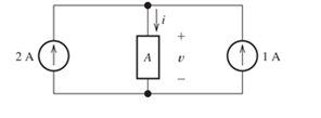
Figure P2.101
- Solve for V with the 2-A source active and the 1-A source zeroed.
Expert Solution & Answer
Want to see the full answer?
Check out a sample textbook solution
Students have asked these similar questions
What is the open loop transfer function and feedback for thia system?
Determine the type of the open loop system.
Find the poles s1 and s2 of the open loop system.
If the input is a step function R(s)=1/s, find the step response c(t) of the open loop.
not use ai please don't
2.
A DC generator is shown below. This DC generator is driven by a prime mover and
rotating in counterclockwise direction. The armature is connected with a load resistor.
(i) Using cross (x) or dot (*) to indicate the current direction of each conductor in the armature.
(ii) If we want to reverse the polarity of the generated armature voltage, what can we do to?
rotation
S
load
N
Chapter 2 Solutions
EBK ELECTRICAL ENGINEERING
Ch. 2 - Reduce each of the networks shown in Figure P2.1...Ch. 2 - A 4- resistance is in series with the parallel...Ch. 2 - Find the equivalent resistance looking into...Ch. 2 - Suppose that we need a resistance of 1.5 k and...Ch. 2 - Find the equivalent resistance between terminals a...Ch. 2 - Find the equivalent resistance between terminals a...Ch. 2 - What resistance in parallel with 120 results in...Ch. 2 - Determine the resistance between terminals a and b...Ch. 2 - Two resistances having values of R and 2R are in...Ch. 2 - A network connected between terminals a and b...
Ch. 2 - Two resistances R1 and R2 are connected in...Ch. 2 - Find the equivalent resistance for the infinite...Ch. 2 - If we connect n 1000- resistances in parallel,...Ch. 2 - The heating element of an electric cook top has...Ch. 2 - We are designing an electric space heater to...Ch. 2 - Sometimes, we can use symmetry considerations to...Ch. 2 - The equivalent resistance between terminals a and...Ch. 2 - Three conductances G1 G2, and G3 are in series....Ch. 2 - Most sources of electrical power behave as...Ch. 2 - The resistance for the network shown in Figure...Ch. 2 - Often, we encounter delta-connected loads such as...Ch. 2 - What are the steps in solving a circuit by network...Ch. 2 - Find the values of i1 and i2 in Figure P2.23....Ch. 2 - Find the voltages v1 and v2 for the circuit shown...Ch. 2 - Find the values of v and i in Figure P2.25. Figure...Ch. 2 - Consider the circuit shown in Figure P2.24....Ch. 2 - Find the voltage v and the currents i1 and 12 for...Ch. 2 - Find the values of vs, v1, and i2 in Figure P2.28....Ch. 2 - Find the values of i1 and i2 in Figure P2.29....Ch. 2 - Consider the cirrcuit shown in Figure P2.30 Find...Ch. 2 - Solve for the values of i1, i2, and the powers for...Ch. 2 - The 12-V source in Figure P2.32 is delivering 36...Ch. 2 - Refer to the circuit shown in Figure P2.33. With...Ch. 2 - Find the values of i1 and i2 in Figure P2.34. Find...Ch. 2 - Find the values of i1 and i2 in Figure P2.35...Ch. 2 - Use the voltage-division principle to calculate...Ch. 2 - Use the current-division principle to calculate i1...Ch. 2 - Use the voltage-division principle to calculate...Ch. 2 - Use the current-division principle to calculate...Ch. 2 - Suppose we need to design a voltage-divider...Ch. 2 - A source supplies 120 V to the series combination...Ch. 2 - We have a 60- resistance, a 20- resistance, and...Ch. 2 - A worker is standing on a wet concrete floor,...Ch. 2 - Suppose we have a load that absorbs power and...Ch. 2 - We have a load resistance of 50 that we wish to...Ch. 2 - We have a load resistance of 1 k that we wish to...Ch. 2 - The circuit of Figure P2.47 is similar to networks...Ch. 2 - Write equations and solve for the node voltages...Ch. 2 - Solve for the node voltages shown in Figure P2.49....Ch. 2 - Solve for the node voltages shown in Figure P2.50....Ch. 2 - Given R1=4 , R2=5 , R2=8 , R4=10 , R5=2 , and...Ch. 2 - Determine the value of i1 in Figure P2.52 using...Ch. 2 - Given R1=15 , R5=5 , R3=20 , R4=10 , R5=8 , R6=4 ,...Ch. 2 - In solving a network, what rule must you observe...Ch. 2 - Use the symbolic features of MATLAB to find an...Ch. 2 - Solve for the values of the node voltages shown in...Ch. 2 - Solve for the node voltages shown in Figure P2.57....Ch. 2 - Solve for the power delivered to the 8- ...Ch. 2 - Solve for the node voltages shown in Figure P2.59....Ch. 2 - Find the equivalent resistance looking into...Ch. 2 - Find the equivalent resistance looking into...Ch. 2 - Figure P2.62 shows an unusual voltage-divider...Ch. 2 - Solve for the node voltages in the circuit of...Ch. 2 - We have a cube with 1- resistances along each...Ch. 2 - Solve for the power delivered to the 15- resistor...Ch. 2 - Determine the value of v2 and the power delivered...Ch. 2 - Use mesh-current analysis to find the value of i1...Ch. 2 - Solve for the power delivered by the voltage...Ch. 2 - Use mesh-current analysis to find the value of v...Ch. 2 - Use mesh-current analysis to find the value of i3...Ch. 2 - Use mesh-current analysis to find the values of i1...Ch. 2 - Find the power delivered by the source and the...Ch. 2 - Use mesh-current analysis to find the values of i1...Ch. 2 - Use mesh-current analysis to find the values of i1...Ch. 2 - The circuit shown in Figure P2.75 is the dc...Ch. 2 - Use MATLAB and mesh-current analysis to determine...Ch. 2 - Connect a 1-V voltage source across terminals a...Ch. 2 - Connect a 1-V voltage source across the terminals...Ch. 2 - Use MATLAB to solve for the mesh currents in...Ch. 2 - Find the Thévenin and Norton equivalent circuits...Ch. 2 - We can model a certain battery as a voltage source...Ch. 2 - Find the Thévenin and Norton equivalent circuits...Ch. 2 - Find the Thévenin and Norton equivalent circuits...Ch. 2 - Find the Thévenin arid Norton equivalent circuits...Ch. 2 - An automotive battery has an open-circuit voltage...Ch. 2 - A certain two-terminal circuit has an open-circuit...Ch. 2 - If we measure the voltage at the terminals of a...Ch. 2 - Find the Thévenin and Norton equivalent circuits...Ch. 2 - Find the maximum power that can be delivered to a...Ch. 2 - Find the maximum power that can be delivered to a...Ch. 2 - Figure P2.91 shows a resistive load RL connected...Ch. 2 - Starling from the Norton equivalent circuit with a...Ch. 2 - A battery can be modeled by a voltage source Vt in...Ch. 2 - Use superposition to find the current i in Figure...Ch. 2 - Solve for is in Figure P2.49 by using...Ch. 2 - Solve the circuit shown in Figure P2.48 by using...Ch. 2 - Solve for i1 in Figure P2.34 by using...Ch. 2 - Another method of solving the circuit of Figure...Ch. 2 - Use the method of Problem P2.98 for the circuit of...Ch. 2 - Solve for the actual value of i6 for the circuit...Ch. 2 - Device A shown in Figure P2.101 has v=3i2 for i 0...Ch. 2 - The Wheatstone bridge shown in Figure 2.66 is...Ch. 2 - The Wheatstone bridge shown in Figure 2.66has...Ch. 2 - In theory, any values can be used for R1 and R3 in...Ch. 2 - Derive expressions for the Thévenin voltage and...Ch. 2 - Derive Equation 2.93 for the bridge circuit of...Ch. 2 - Prob. 2.107PCh. 2 - Explain what would happen if, in wiring the bridge...Ch. 2 - Match each entry in Table T2.1(a) with the best...Ch. 2 - Consider the circuit of Figure T2.2 with vs=96V ,...Ch. 2 - Write MATLAB code to solve for the node voltages...Ch. 2 - Write a set of equations that can be used to solve...Ch. 2 - Determine the Thévenin and Norton equivalent...Ch. 2 - According to the superposition principle, what...Ch. 2 - Determine the equivalent resistance between...Ch. 2 - Transform the 2-A current source and 6- ...
Knowledge Booster


Learn more about
Need a deep-dive on the concept behind this application? Look no further. Learn more about this topic, electrical-engineering and related others by exploring similar questions and additional content below.Similar questions
- 6. The figures below show the equivalent circuit of a separately excited DC generator and the approximate relationship between the flux of main field and exciting current. The field current I can be regulated by the variable resistor Ry, and the battery voltage supplying power to the exciter is 12V. The armature resistance Ro is 20, and the load is 182. For the DC generator, we aim to keep the voltage across the load (RL) constant in different speed range conditions. In the beginning, the flux is 0.12 Wb, the DC generator speed is 1000 rpm, and the generated voltage E。 is 100 V. Calculate: (1) The current flowing through the load. (2) When the speed of generator changes to 1500 rpm, how should we adjust the exciting current Ix to ensure Ę is still 100 V. (Hint: E₁ = Zno/60) (3) When the speed of generator changes to 500 rpm, how should we adjust the exciting current Ix to ensure Eo is still 100 V. (Hint: Eo = Zno/60) Rf ww (Wb) 0.17 0.15 12 V 1x F ele 1 1 2 ell Eo Ro ww 9 w RL Ix (A)arrow_forward7. For a shunt excited motor, the maximum allowable current is twice of the full-load current. The full-load current is 10 A. The equivalent circuit of this motor is also shown below. The rheostat can change the resistance by moving the slider (contact). The counter electromotive force (CEMF) for this motor is 100 V at 1000 rpm. The power supply E, is 200 V. In this case: (1) Calculate the minimum resistor value R at 0 rpm ensuing the motor is running within the safe range, and calculate the power consumed by the rheostat R. (2) Calculate the minimum effective resistor value R at 100 rpm ensuing the motor is running within the safe range, and calculate the power consumed by the rheostat R and the delivered mechanical power. (3) Calculate the minimum resistor value R at 500 rpm ensuing the motor is running within the safe range, and calculate the power consumed by the rheostat R the delivered mechanical power. shunt field R armature rheostat Es + Eoarrow_forward4. For a general DC generator, we aim to achieve constant output voltage at different rotating speeds. (1) List two factors influencing the output voltage for a given DC generator. (2) How does the change of the load (assuming the load is the current flowing though the resistor) will impact on the generated voltage for (a) separately excited DC generator, (b) Shunt DC generator, and (c) cumulative compound DC generator?arrow_forward
- 3. A DC motor is shown below. The armature is supplied by an external battery, and the current flowing direction of each conduction is depicted in the figure. (i) Draw the Lorentz force direction applied on each conductor in the armature. (ii) In which direction will the motor spin? What can we do to reverse the spinning direction? S Narrow_forward5. conditions. For a general DC motor, we aim to control the speed of the motor at different loading (1) List two factors influencing the motor speed for a given DC motor. (2) List three ways to stop a motor and comment on each method?arrow_forwardSolve by Pen and Paper not using chatgptarrow_forward
arrow_back_ios
SEE MORE QUESTIONS
arrow_forward_ios
Recommended textbooks for you
 Introductory Circuit Analysis (13th Edition)Electrical EngineeringISBN:9780133923605Author:Robert L. BoylestadPublisher:PEARSON
 Delmar's Standard Textbook Of ElectricityElectrical EngineeringISBN:9781337900348Author:Stephen L. HermanPublisher:Cengage Learning
 Programmable Logic ControllersElectrical EngineeringISBN:9780073373843Author:Frank D. PetruzellaPublisher:McGraw-Hill Education
 Fundamentals of Electric CircuitsElectrical EngineeringISBN:9780078028229Author:Charles K Alexander, Matthew SadikuPublisher:McGraw-Hill Education
 Electric Circuits. (11th Edition)Electrical EngineeringISBN:9780134746968Author:James W. Nilsson, Susan RiedelPublisher:PEARSON
 Engineering ElectromagneticsElectrical EngineeringISBN:9780078028151Author:Hayt, William H. (william Hart), Jr, BUCK, John A.Publisher:Mcgraw-hill Education,
Introductory Circuit Analysis (13th Edition)
Electrical Engineering
ISBN:9780133923605
Author:Robert L. Boylestad
Publisher:PEARSON
Delmar's Standard Textbook Of Electricity
Electrical Engineering
ISBN:9781337900348
Author:Stephen L. Herman
Publisher:Cengage Learning
Programmable Logic Controllers
Electrical Engineering
ISBN:9780073373843
Author:Frank D. Petruzella
Publisher:McGraw-Hill Education
Fundamentals of Electric Circuits
Electrical Engineering
ISBN:9780078028229
Author:Charles K Alexander, Matthew Sadiku
Publisher:McGraw-Hill Education
Electric Circuits. (11th Edition)
Electrical Engineering
ISBN:9780134746968
Author:James W. Nilsson, Susan Riedel
Publisher:PEARSON
Engineering Electromagnetics
Electrical Engineering
ISBN:9780078028151
Author:Hayt, William H. (william Hart), Jr, BUCK, John A.
Publisher:Mcgraw-hill Education,
Current Divider Rule; Author: Neso Academy;https://www.youtube.com/watch?v=hRU1mKWUehY;License: Standard YouTube License, CC-BY