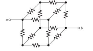
Sometimes, we can use symmetry considerations to find the resistance of a circuit that cannot be reduced by series or parallel combinations. A classic problem of this type is illustrated in Figure P2.16. Twelve 1- Ω resistors are arranged on the edges of a cube, and terminals a and b are connected to diagonally opposite corners of the cube. The problem is to find the resistance between the terminals. Approach the problem this way: Assume that 1 A of current enters terminal a and exits through terminal b. Then, the voltage between terminals a and b is equal to the unknown resistance. By symmetry considerations, we can find the current in each resistor. Then, using KVL, we can find the voltage between a and b. Figure P2.16 Each resistor has a value of 1 Ω .
Sometimes, we can use symmetry considerations to find the resistance of a circuit that cannot be reduced by series or parallel combinations. A classic problem of this type is illustrated in Figure P2.16. Twelve 1- Ω resistors are arranged on the edges of a cube, and terminals a and b are connected to diagonally opposite corners of the cube. The problem is to find the resistance between the terminals. Approach the problem this way: Assume that 1 A of current enters terminal a and exits through terminal b. Then, the voltage between terminals a and b is equal to the unknown resistance. By symmetry considerations, we can find the current in each resistor. Then, using KVL, we can find the voltage between a and b. Figure P2.16 Each resistor has a value of 1 Ω .
Solution Summary: The circuit is shown in Figure 1. Mark the nodes and the current directions and redraw the circuit.
Sometimes, we can use symmetry considerations to find the resistance of a circuit that cannot be reduced by series or parallel combinations. A classic problem of this type is illustrated in Figure P2.16. Twelve 1-
Ω
resistors are arranged on the edges of a cube, and terminals a and b are connected to diagonally opposite corners of the cube. The problem is to find the resistance between the terminals. Approach the problem this way: Assume that 1 A of current enters terminal a and exits through terminal b. Then, the voltage between terminals a and b is equal to the unknown resistance. By symmetry considerations, we can find the current in each resistor. Then, using KVL, we can find the voltage between a and b.
R1 is 978 ohms R2 is 2150 ohms R3 is 4780
R1 is parallel to R2 and R2 is parallel to R3 and R1 and R3 are in series
Q7 For the circuit shown in Fig. 2.20, the transistors are identical and have the following
parameters: hfe = 50, hie = 1.1K, hre = 0, and hoe = 0. Calculate Auf, Rif and Rof.
Ans: 45.4; 112 KQ; 129.
25 V
10k
47k
4.7k
Vo
150k
w
Vs
47k
4.7k
W
22
5μF
33k
50uF
50μF
4.7k
4.7k
R₁
Rof
Rif
R1000
Fig. 2.20 Circuit for Q7.
Q6)) The transistors in the feedback amplifier shown are
identical, and their h-parameters are..
hie = 1.1k, hfe = 50, hre=o, and hoe = 0. Calculate Auf, Rif and
Rof. {Ans: 6031583; 4. Kor.
Is 4
4.7 k
www
4.7k
91k 4.7k
91k
10k
1k.
10k
21000
4.7k
w
15k
Fig. 2.19 Circuit for Q6.
Need a deep-dive on the concept behind this application? Look no further. Learn more about this topic, electrical-engineering and related others by exploring similar questions and additional content below.


 Introductory Circuit Analysis (13th Edition)Electrical EngineeringISBN:9780133923605Author:Robert L. BoylestadPublisher:PEARSON
 Delmar's Standard Textbook Of ElectricityElectrical EngineeringISBN:9781337900348Author:Stephen L. HermanPublisher:Cengage Learning
 Programmable Logic ControllersElectrical EngineeringISBN:9780073373843Author:Frank D. PetruzellaPublisher:McGraw-Hill Education
 Fundamentals of Electric CircuitsElectrical EngineeringISBN:9780078028229Author:Charles K Alexander, Matthew SadikuPublisher:McGraw-Hill Education
 Electric Circuits. (11th Edition)Electrical EngineeringISBN:9780134746968Author:James W. Nilsson, Susan RiedelPublisher:PEARSON
 Engineering ElectromagneticsElectrical EngineeringISBN:9780078028151Author:Hayt, William H. (william Hart), Jr, BUCK, John A.Publisher:Mcgraw-hill Education,