
EBK ELECTRICAL ENGINEERING
7th Edition
ISBN: 8220106714201
Author: HAMBLEY
Publisher: YUZU
expand_more
expand_more
format_list_bulleted
Concept explainers
Videos
Textbook Question
Chapter 2, Problem 2.23P
Find the values of i1 and i2 in Figure P2.23.
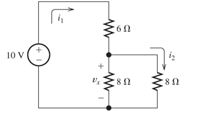
Figure P2.23
Expert Solution & Answer

Learn your wayIncludes step-by-step video

schedule02:46
Students have asked these similar questions
I need help in construct a method in matlab to find the voltage of VR1 to VR4, rhe current, and the power base on that circuit
Nominal or Theortical:
E1 = 3V , E2 = 9V, E3 = 1.5V
R1 =10Kohm, R2 =2Kohm, R3 =1Kohm, R4 =16Kohm
Procedure:-
1- Connect the cct. shown in fig.(2).
a
ADDs Ds
Fig.(2)
2-For resistive load, measure le output voltage by using oscilloscope; then sketch this
wave.
3- Measure the average values f VL and IL:
4- Repeat steps 2 & 3 but for RL load.
Report:-
1- Calculate the D.C. output vcl age theoretically and compare it with the test value.
2- Calculate the harmonic cont :nts of the load voltage, and explain how filter
components may be selected.
3- Compare between the three-phase half & full-wave uncontrolled bridge rectifier.
4- Draw the waveform for the c:t. shown in fig.(2) but after replaced Di and D3 by
thyristors with a = 30° and a2 = 90°
5- Draw the waveform for the cct. shown in fig.(2) but after replace the 6-diodes by 6-
thyristor.
6- Discuss your results. Draw the waves on graph paper
please
Please solve No. 4
and 5
not use ai please
chat gpt
How to draw this in LtSpice
Chapter 2 Solutions
EBK ELECTRICAL ENGINEERING
Ch. 2 - Reduce each of the networks shown in Figure P2.1...Ch. 2 - A 4- resistance is in series with the parallel...Ch. 2 - Find the equivalent resistance looking into...Ch. 2 - Suppose that we need a resistance of 1.5 k and...Ch. 2 - Find the equivalent resistance between terminals a...Ch. 2 - Find the equivalent resistance between terminals a...Ch. 2 - What resistance in parallel with 120 results in...Ch. 2 - Determine the resistance between terminals a and b...Ch. 2 - Two resistances having values of R and 2R are in...Ch. 2 - A network connected between terminals a and b...
Ch. 2 - Two resistances R1 and R2 are connected in...Ch. 2 - Find the equivalent resistance for the infinite...Ch. 2 - If we connect n 1000- resistances in parallel,...Ch. 2 - The heating element of an electric cook top has...Ch. 2 - We are designing an electric space heater to...Ch. 2 - Sometimes, we can use symmetry considerations to...Ch. 2 - The equivalent resistance between terminals a and...Ch. 2 - Three conductances G1 G2, and G3 are in series....Ch. 2 - Most sources of electrical power behave as...Ch. 2 - The resistance for the network shown in Figure...Ch. 2 - Often, we encounter delta-connected loads such as...Ch. 2 - What are the steps in solving a circuit by network...Ch. 2 - Find the values of i1 and i2 in Figure P2.23....Ch. 2 - Find the voltages v1 and v2 for the circuit shown...Ch. 2 - Find the values of v and i in Figure P2.25. Figure...Ch. 2 - Consider the circuit shown in Figure P2.24....Ch. 2 - Find the voltage v and the currents i1 and 12 for...Ch. 2 - Find the values of vs, v1, and i2 in Figure P2.28....Ch. 2 - Find the values of i1 and i2 in Figure P2.29....Ch. 2 - Consider the cirrcuit shown in Figure P2.30 Find...Ch. 2 - Solve for the values of i1, i2, and the powers for...Ch. 2 - The 12-V source in Figure P2.32 is delivering 36...Ch. 2 - Refer to the circuit shown in Figure P2.33. With...Ch. 2 - Find the values of i1 and i2 in Figure P2.34. Find...Ch. 2 - Find the values of i1 and i2 in Figure P2.35...Ch. 2 - Use the voltage-division principle to calculate...Ch. 2 - Use the current-division principle to calculate i1...Ch. 2 - Use the voltage-division principle to calculate...Ch. 2 - Use the current-division principle to calculate...Ch. 2 - Suppose we need to design a voltage-divider...Ch. 2 - A source supplies 120 V to the series combination...Ch. 2 - We have a 60- resistance, a 20- resistance, and...Ch. 2 - A worker is standing on a wet concrete floor,...Ch. 2 - Suppose we have a load that absorbs power and...Ch. 2 - We have a load resistance of 50 that we wish to...Ch. 2 - We have a load resistance of 1 k that we wish to...Ch. 2 - The circuit of Figure P2.47 is similar to networks...Ch. 2 - Write equations and solve for the node voltages...Ch. 2 - Solve for the node voltages shown in Figure P2.49....Ch. 2 - Solve for the node voltages shown in Figure P2.50....Ch. 2 - Given R1=4 , R2=5 , R2=8 , R4=10 , R5=2 , and...Ch. 2 - Determine the value of i1 in Figure P2.52 using...Ch. 2 - Given R1=15 , R5=5 , R3=20 , R4=10 , R5=8 , R6=4 ,...Ch. 2 - In solving a network, what rule must you observe...Ch. 2 - Use the symbolic features of MATLAB to find an...Ch. 2 - Solve for the values of the node voltages shown in...Ch. 2 - Solve for the node voltages shown in Figure P2.57....Ch. 2 - Solve for the power delivered to the 8- ...Ch. 2 - Solve for the node voltages shown in Figure P2.59....Ch. 2 - Find the equivalent resistance looking into...Ch. 2 - Find the equivalent resistance looking into...Ch. 2 - Figure P2.62 shows an unusual voltage-divider...Ch. 2 - Solve for the node voltages in the circuit of...Ch. 2 - We have a cube with 1- resistances along each...Ch. 2 - Solve for the power delivered to the 15- resistor...Ch. 2 - Determine the value of v2 and the power delivered...Ch. 2 - Use mesh-current analysis to find the value of i1...Ch. 2 - Solve for the power delivered by the voltage...Ch. 2 - Use mesh-current analysis to find the value of v...Ch. 2 - Use mesh-current analysis to find the value of i3...Ch. 2 - Use mesh-current analysis to find the values of i1...Ch. 2 - Find the power delivered by the source and the...Ch. 2 - Use mesh-current analysis to find the values of i1...Ch. 2 - Use mesh-current analysis to find the values of i1...Ch. 2 - The circuit shown in Figure P2.75 is the dc...Ch. 2 - Use MATLAB and mesh-current analysis to determine...Ch. 2 - Connect a 1-V voltage source across terminals a...Ch. 2 - Connect a 1-V voltage source across the terminals...Ch. 2 - Use MATLAB to solve for the mesh currents in...Ch. 2 - Find the Thévenin and Norton equivalent circuits...Ch. 2 - We can model a certain battery as a voltage source...Ch. 2 - Find the Thévenin and Norton equivalent circuits...Ch. 2 - Find the Thévenin and Norton equivalent circuits...Ch. 2 - Find the Thévenin arid Norton equivalent circuits...Ch. 2 - An automotive battery has an open-circuit voltage...Ch. 2 - A certain two-terminal circuit has an open-circuit...Ch. 2 - If we measure the voltage at the terminals of a...Ch. 2 - Find the Thévenin and Norton equivalent circuits...Ch. 2 - Find the maximum power that can be delivered to a...Ch. 2 - Find the maximum power that can be delivered to a...Ch. 2 - Figure P2.91 shows a resistive load RL connected...Ch. 2 - Starling from the Norton equivalent circuit with a...Ch. 2 - A battery can be modeled by a voltage source Vt in...Ch. 2 - Use superposition to find the current i in Figure...Ch. 2 - Solve for is in Figure P2.49 by using...Ch. 2 - Solve the circuit shown in Figure P2.48 by using...Ch. 2 - Solve for i1 in Figure P2.34 by using...Ch. 2 - Another method of solving the circuit of Figure...Ch. 2 - Use the method of Problem P2.98 for the circuit of...Ch. 2 - Solve for the actual value of i6 for the circuit...Ch. 2 - Device A shown in Figure P2.101 has v=3i2 for i 0...Ch. 2 - The Wheatstone bridge shown in Figure 2.66 is...Ch. 2 - The Wheatstone bridge shown in Figure 2.66has...Ch. 2 - In theory, any values can be used for R1 and R3 in...Ch. 2 - Derive expressions for the Thévenin voltage and...Ch. 2 - Derive Equation 2.93 for the bridge circuit of...Ch. 2 - Prob. 2.107PCh. 2 - Explain what would happen if, in wiring the bridge...Ch. 2 - Match each entry in Table T2.1(a) with the best...Ch. 2 - Consider the circuit of Figure T2.2 with vs=96V ,...Ch. 2 - Write MATLAB code to solve for the node voltages...Ch. 2 - Write a set of equations that can be used to solve...Ch. 2 - Determine the Thévenin and Norton equivalent...Ch. 2 - According to the superposition principle, what...Ch. 2 - Determine the equivalent resistance between...Ch. 2 - Transform the 2-A current source and 6- ...
Additional Engineering Textbook Solutions
Find more solutions based on key concepts
For the case of plane stress, show that Hookes law can be written as x=E(1v2)(x+vy),y=E(1v2)(y+vx)
Mechanics of Materials (10th Edition)
A ______ structure can execute a set of statements only under certain circumstances. a. sequence b. circumstant...
Starting Out with Python (4th Edition)
In the text, JUMP instructions were expressed by identifying the destination explicitly by stating the name (or...
Computer Science: An Overview (13th Edition) (What's New in Computer Science)
12. Consider the following strange, but true, units:
1 arroba =11.5 kilograms [kg] 1 peck = 9 liters [L]
A bask...
Thinking Like an Engineer: An Active Learning Approach (4th Edition)
What would the following statement, when used in a Java program, display on the screen? system.out.println(Java...
Java: An Introduction to Problem Solving and Programming (8th Edition)
2-1 List the five types of measurements that form the
basis of traditional ptane surveying-
Elementary Surveying: An Introduction To Geomatics (15th Edition)
Knowledge Booster


Learn more about
Need a deep-dive on the concept behind this application? Look no further. Learn more about this topic, electrical-engineering and related others by exploring similar questions and additional content below.Similar questions
- 4. Discussion: Compare between theoretical effect of KI at first order and second order systems regarding steady-state errors and transient responses with the practical In Experiment Integral Controllerarrow_forwardI would appreciate your help in solving the questions and drawing.arrow_forward498 FET AMPLIFIERS AND SWITCHING CIRCUITS FIGURE 9-54 FIGURE 0.55 5. Identify the type of FET and its bias arrangement in Figure 9-54. Ideally, what is Vas? 6. Calculate the dc voltages from each terminal to ground for the FETs in Figure 9-54. +15 V -10 V +12 V 8 mA Ro 3 mA 1.0 ΚΩ Rp 1.5 ΚΩ Rp 6 mA R₁ 1.0 ΚΩ 10 ΚΩ RG * 10 ΜΩ RG 10 ΜΩ ww Rs R₂ • 330 Ω · 4.7 ΚΩ (a) (b) 7. Identify each characteristic curve in Figure 9-55 by the type of FET that it represents.arrow_forward
- Can you help me achieve the requirements using Arduino? I have encountered some issues with these requirements. 1. Functionality:** The system must control 3 LEDS (Red, Green, and Blue) to produce at least 4 different lighting modes: a. **Mode 1: All LEDs blink simultaneously at 1-second intervals. b. Mode 2: LEDs blink in sequence (Red → Green → Blue) with a 500ms delay between each LED. c. **Mode 3:** LEDs fade in and out smoothly (PWM control) in the order Red Green → Blue. d. **Mode 4: Custom mode (e.g., random blinking or a pattern of your choice). 2. Constraints:** -Use only one push button to cycle through the modes. -The system must operate within a 5V power supply. -The total current drawn by the LEDs must not exceed 100mA. -Use resistors to limit the current through each LED appropriately. 3. Design Process:** -Analysis: Calculate the required resistor values for each LED to ensure they operate within their specified current limits. Synthesis: Develop a circuit schematic and…arrow_forwardnot use ai pleasearrow_forwardProcedure:- 1- Connect the cct. shown in fig.(2). a ADDS DS Fig.(2) 2-For resistive load, measure le output voltage by using oscilloscope ;then sketch this wave. 3- Measure the average values ::f VL and IL: 4- Repeat steps 2 & 3 but for RL load. Report:- 1- Calculate the D.C. output vcl age theoretically and compare it with the test value. 2- Calculate the harmonic cont :nts of the load voltage, and explain how filter components may be selected. 3- Compare between the three-phase half & full-wave uncontrolled bridge rectifier. 4- Draw the waveform for the c:t. shown in fig.(2) but after replaced Di and D3 by thyristors with a 30° and a2 = 90° 5- Draw the waveform for the cct. shown in fig.(2) but after replace the 6-diodes by 6- thyristor. 6- Discuss your results. Please solve No. 4 and 5arrow_forward
- a.) Sketch each of the following signals, and starting with the defining relation, finds its Fourier transform X (w) - a) x(t) = rect(t − 3) b) x(t)=3t rect(t) c) x(t) = 2te 3u1(t) d) x(t) = e−2|t| b.) Sketch the magnitude and phase spectrum for the four signals in Problem (a). c) Calculate energy using time-domain and frequency domain formulas for signals in Problem (a) and (b). Confirm Parseval's theorem using these calculations.arrow_forwardI need help in construct a method in matlab to find the voltage of VR1 to VR4, rhe current, and the power base on that circuit Nominal or Theortical: E1 = 3V , E2 = 9V, E3 = 1.5V R1 =10Kohm, R2 =2Kohm, R3 =1Kohm, R4 =16Kohmarrow_forwardI have a question based on the mesh anaylsis, why does current around R1 and the same as R3?arrow_forward
- 1. Compute the output signals S and T for the circuit. Input signals P = 1, Q = 1, and R = 1. C₁ P half-adder #1 R AND -S C₁₂ half-adder #2 2. Use 8-bit representations to compute the following sum. Show all work. 57+(-118) 3. Find a counterexample to show that the following statement is false: 1 Vx Є R, x>- χ T 4. Is the proposed negation correct? If yes, provide a sound reasoning. If not, provide a sound reasoning and write the correct negation. Statement: For all integers n, if n² is even then n is even. Negation: For all integers n, if n² is even then n is not even.arrow_forwardnot use aiarrow_forward2. (35 points) Use you program to investigative properties of a four step linear pathway. Just extend the model given in question 1 to include an additional two species x2 and x3. You can assume simple irreversible mass-action kinetic on each reaction. I recommend you use the following values for the rate constants: 1 = 0.6; k2 = 1.8; k3 = 0.5; k40.04. This will enable you to more easily answer the following questions. You can also assume that the input is the source X and you can set its value to one. You may find that the plot of the phase change at x3 is broken at -180 degrees because it wraps around. To avoid this you can use the method: phase = np.unwrap(phase) to make sure the phase plot is continuous. [10] i) Compute and show the Bode plots for x1, x2 and x3 with respect to the input Xo. [5] ii) Do you see a pattern with the maximum phase shifts as you move from x₁ to x3? [10] iii) Can you explain this pattern? [5] iv) What would you predict would be the maximum phase shift for…arrow_forward
arrow_back_ios
SEE MORE QUESTIONS
arrow_forward_ios
Recommended textbooks for you
 Power System Analysis and Design (MindTap Course ...Electrical EngineeringISBN:9781305632134Author:J. Duncan Glover, Thomas Overbye, Mulukutla S. SarmaPublisher:Cengage Learning
Power System Analysis and Design (MindTap Course ...
Electrical Engineering
ISBN:9781305632134
Author:J. Duncan Glover, Thomas Overbye, Mulukutla S. Sarma
Publisher:Cengage Learning
Nodal Analysis for Circuits Explained; Author: Engineer4Free;https://www.youtube.com/watch?v=f-sbANgw4fo;License: Standard Youtube License