
MICROELECT. CIRCUIT ANALYSIS&DESIGN (LL)
4th Edition
ISBN: 9781266368622
Author: NEAMEN
Publisher: MCG
expand_more
expand_more
format_list_bulleted
Concept explainers
Videos
Textbook Question
Chapter 2, Problem 2.48P
The diode cut−in voltage for each diode in the circuit shown in Figure P2.48 is 0.7V. Determine the value of R such that (a)
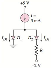
Figure P2.48
Expert Solution & Answer
Want to see the full answer?
Check out a sample textbook solution
Students have asked these similar questions
Qs For the network of Fig. 1.45:
a- Determine fH, and fHo
b- Find fp and fr
c- Sketch the frequency response for the high-frequency region using a Bode plot and
determine the cutoff frequency.
Ans: 2.87 MHz, 185.78 MHz, 1.05 MHz, 105 MHz.
14V
CWF8pF
Cwo-10pF
Cbc-20 pF
Cbe=30pF
120 ΚΩ
Co=12pF
1 ΚΩ
B-100
0.1 µF
Vs
0.1 HF
Z;
Vo
www
30 kQ
2.2 ΚΩ
€ 8.2 kQ
Fig. 1.45 Circuit for C
5 A
Q4) A thin ring of radius 5 cm is placed on plane z = 1 cm so that its center is at
(0,0,1 cm). If the ring carries 50 mA along a^, find H at (0,0,a).
Q6) Find the current density J for the magnetic field intensity vectors:
(a) H = x²ya, + y²zay - 2xza,
(b) H = p²zap + p³a + 3pz²az
sin
cos
(c) H =
a,
2
+2
Chapter 2 Solutions
MICROELECT. CIRCUIT ANALYSIS&DESIGN (LL)
Ch. 2 - Repeat Example 2.1 if the input voltage is...Ch. 2 - Consider the bridge circuit shown in Figure 2.6(a)...Ch. 2 - Assume the input signal to a rectifier circuit has...Ch. 2 - The input voltage to the halfwave rectifier in...Ch. 2 - Consider the circuit in Figure 2.4. The input...Ch. 2 - The circuit in Figure 2.5(a) is used to rectify a...Ch. 2 - The secondary transformer voltage of the rectifier...Ch. 2 - Determine the fraction (percent) of the cycle that...Ch. 2 - The Zener diode regulator circuit shown in Figure...Ch. 2 - Repeat Example 2.6 for rz=4 . Assume all other...
Ch. 2 - Consider the circuit shown in Figure 2.19. Let...Ch. 2 - Suppose the currentlimiting resistor in Example...Ch. 2 - Suppose the power supply voltage in the circuit...Ch. 2 - Design a parallelbased clipper that will yield the...Ch. 2 - Sketch the steadystate output voltage for the...Ch. 2 - Consider the circuit in Figure 2.23(a). Let R1=5k...Ch. 2 - Determine the steadystate output voltage O for the...Ch. 2 - Design a parallelbased clipper circuit that will...Ch. 2 - Consider the circuit shown in Figure 2.38, in...Ch. 2 - Consider the circuit shown in Figure 2.39. The...Ch. 2 - Repeat Example 2.11 for the case when R1=8k ,...Ch. 2 - The cutin voltage of each diode in the circuit...Ch. 2 - Prob. 2.12TYUCh. 2 - Consider the OR logic circuit shown in Figure...Ch. 2 - Consider the AND logic circuit shown in Figure...Ch. 2 - (a) Photons with an energy of hv=2eV are incident...Ch. 2 - Determine the value of resistance R required to...Ch. 2 - What characteristic of a diode is used in the...Ch. 2 - Prob. 2RQCh. 2 - Describe a simple fullwave diode rectifier circuit...Ch. 2 - Prob. 4RQCh. 2 - Prob. 5RQCh. 2 - Describe a simple Zener diode voltage reference...Ch. 2 - What effect does the Zener diode resistance have...Ch. 2 - What are the general characteristics of diode...Ch. 2 - Describe a simple diode clipper circuit that...Ch. 2 - Prob. 10RQCh. 2 - What one circuit element, besides a diode, is...Ch. 2 - Prob. 12RQCh. 2 - Describe a diode OR logic circuit. Compare a logic...Ch. 2 - Describe a diode AND logic circuit. Compare a...Ch. 2 - Describe a simple circuit that can be used to turn...Ch. 2 - Consider the circuit shown in Figure P2.1. Let...Ch. 2 - For the circuit shown in Figure P2.1, show that...Ch. 2 - A halfwave rectifier such as shown in Figure...Ch. 2 - Consider the battery charging circuit shown in...Ch. 2 - Figure P2.5 shows a simple fullwave battery...Ch. 2 - The fullwave rectifier circuit shown in Figure...Ch. 2 - The input signal voltage to the fullwave rectifier...Ch. 2 - The output resistance of the fullwave rectifier in...Ch. 2 - Repeat Problem 2.8 for the halfwave rectifier in...Ch. 2 - Consider the halfwave rectifier circuit shown in...Ch. 2 - The parameters of the halfwave rectifier circuit...Ch. 2 - The fullwave rectifier circuit shown in Figure...Ch. 2 - Consider the fullwave rectifier circuit in Figure...Ch. 2 - The circuit in Figure P2.14 is a complementary...Ch. 2 - Prob. 2.15PCh. 2 - A fullwave rectifier is to be designed using the...Ch. 2 - Prob. 2.17PCh. 2 - (a) Sketch o versus time for the circuit in Figure...Ch. 2 - Consider the circuit shown in Figure P2.19. The...Ch. 2 - Consider the Zener diode circuit shown in Figure...Ch. 2 - Consider the Zener diode circuit shown in Figure...Ch. 2 - In the voltage regulator circuit in Figure P2.21,...Ch. 2 - A Zener diode is connected in a voltage regulator...Ch. 2 - Consider the Zener diode circuit in Figure 2.19 in...Ch. 2 - Design a voltage regulator circuit such as shown...Ch. 2 - The percent regulation of the Zener diode...Ch. 2 - A voltage regulator is to have a nominal output...Ch. 2 - Consider the circuit in Figure P2.28. Let V=0 ....Ch. 2 - The secondary voltage in the circuit in Figure...Ch. 2 - The parameters in the circuit shown in Figure...Ch. 2 - Consider the circuit in Figure P2.31. Let V=0 (a)...Ch. 2 - Prob. 2.32PCh. 2 - Each diode cutin voltage is 0.7 V for the circuits...Ch. 2 - The diode in the circuit of Figure P2.34(a) has...Ch. 2 - Consider the circuits shown in Figure P2.35. Each...Ch. 2 - Plot O for each circuit in Figure P2.36 for the...Ch. 2 - Consider the parallel clipper circuit in Figure...Ch. 2 - A car’s radio may be subjected to voltage spikes...Ch. 2 - Sketch the steadystate output voltage O versus...Ch. 2 - Prob. D2.40PCh. 2 - Design a diode clamper to generate a steadystate...Ch. 2 - For the circuit in Figure P2.39(b), let V=0 and...Ch. 2 - Repeat Problem 2.42 for the circuit in Figure...Ch. 2 - The diodes in the circuit in Figure P2.44 have...Ch. 2 - In the circuit in Figure P2.45 the diodes have the...Ch. 2 - The diodes in the circuit in Figure P2.46 have the...Ch. 2 - Consider the circuit shown in Figure P2.47. Assume...Ch. 2 - The diode cutin voltage for each diode in the...Ch. 2 - Consider the circuit in Figure P2.49. Each diode...Ch. 2 - Assume V=0.7V for each diode in the circuit in...Ch. 2 - The cutin voltage of each diode in the circuit...Ch. 2 - Let V=0.7V for each diode in the circuit in Figure...Ch. 2 - For the circuit shown in Figure P2.54, let V=0.7V...Ch. 2 - Assume each diode cutin voltage is V=0.7V for the...Ch. 2 - If V=0.7V for the diode in the circuit in Figure...Ch. 2 - Let V=0.7V for the diode in the circuit in Figure...Ch. 2 - Each diode cutin voltage in the circuit in Figure...Ch. 2 - Let V=0.7V for each diode in the circuit shown in...Ch. 2 - Consider the circuit in Figure P2.61. The output...Ch. 2 - Consider the circuit in Figure P2.62. The output...Ch. 2 - Prob. 2.63PCh. 2 - Consider the circuit shown in Figure P2.64. The...Ch. 2 - The lightemitting diode in the circuit shown in...Ch. 2 - The parameters of D1 and D2 in the circuit shown...Ch. 2 - If the resistor in Example 2.12 is R=2 and the...Ch. 2 - Consider the photodiode circuit shown in Figure...Ch. 2 - Consider the fullwave bridge rectifier circuit....Ch. 2 - Design a simple dc voltage source using a...Ch. 2 - A clipper is to be designed such that O=2.5V for...Ch. 2 - Design a circuit to provide the voltage transfer...
Knowledge Booster


Learn more about
Need a deep-dive on the concept behind this application? Look no further. Learn more about this topic, electrical-engineering and related others by exploring similar questions and additional content below.Similar questions
- Q2) Line x = 0, y=0,0arrow_forwardQ4) Given the magnetic vector potential: A = y²z ax-(x + 1)z² az A/m Find(a) the magnetic flux density; (b)the magnetic flux through a square loop described by 0≤x≤1, 0 ≤ y ≤1, z=2.arrow_forwardQ5) Consider the following arbitrary fields. Find out which of them can possibly represent electrostatic or magnetostatic field in free space. (a) A = y cos axa, + (y + ea, (b) B 20 р (c) C = r² sin 0 aarrow_forwardEx. 12 plane y=l carries current k = 50āz Find at- roro) ره α)- ⑥(1.5-3). Hw marrow_forwardPlease, my dear teacher, solve the question on a piece of paper, not with artificial intelligence, then show the final matrix in the solution. Subject the Control Systemarrow_forwardAn Aluminum wire 2250Ft long cannot have a resistance greater than 0.2 ohms. What is the minimum size of wire that may be used?arrow_forwardCalculate the resistance for Aluminum wire, 8 AWG with a length of 1000 FT*arrow_forwardIntroduction The circuit of Fig. 1 is required to be modeled using a state - space representation, where 2 states will be used, based on the number of the energy - storing elements of the circuit, the capacitor and the inductor. u(t) + ΙΩ www 13 F 5 Ω it (t) www vc(t) 1 H Figure 1: LCR circuit The input signal to the circuit is the voltage u(t) in Volts and the output signal is the voltage across the capacitor, vc(t). Questions 1. Choice of system states: Choose appropriate signals for the 2 states of the system. x₁(t) = i₁(t) x₂ (t) =arrow_forward5. State transition matrix: (t), which is defined as, Calculate analytically the state transition matrix (t) = et = L¯¹{(sI – A)¯¹} Show that the answer is the following, 1 e-4t cos(√2t) - e-4 sin(√2 t) 1 e -4t √2 (t) = et -3 1 -4t sin (√2 t) e COS -4t cos (√2t) + - e sin(√2 t) 2-4t sin(√2 t)| Calculate the following: (SI - A)-1= Use the completion - in - the-square technique (CASE 3) to calculate the inverse Laplace: L¯¹{(SI - A)¯¹} =arrow_forwardA single-core cable working on 66 kV has a conductor diameter of 2 cm and the sheath of inside diameter is 10 cm. If two metallic intersheaths of diameters 5 cm, 8 cm respectively are used for grading the cable.. If the maximum electric stress is the same for each layers. 1- Find the voltage of each metallic intersheaths. 2- Find the thickness of each layers.arrow_forwardkΩarrow_forwardNO AI PLEASEarrow_forwardarrow_back_iosSEE MORE QUESTIONSarrow_forward_ios
Recommended textbooks for you

Diodes Explained - The basics how diodes work working principle pn junction; Author: The Engineering Mindset;https://www.youtube.com/watch?v=Fwj_d3uO5g8;License: Standard Youtube License