
Concept explainers
Videos
Consider the circuit in Figure P2.62. The output of a diode AND logic gate is connected to the input of a second diode AND logic gate. Assume
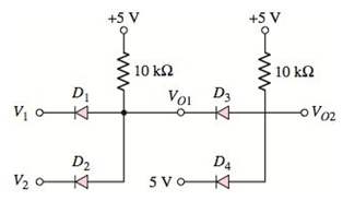
Figure P2.62
(a)
Values of output voltages
Answer to Problem 2.62P
The values of output voltages are
The values of output voltages are
The values of output voltages are
Explanation of Solution
Given:
The given circuit is shown below.
Voltages given:
Calculation:
(i) Assume voltage
The entire circuit can be divided into two parts.
Now considering the first part,
On considering the connection of Diodes it is known that diodes are connected in reverse bias.
So, taking considerations from the first part, it is concluded that the output,
Hence, if the inputs of circuit are
Similarly, if the inputs of circuit are
Similarly, if the inputs of circuit are
Similarly, if the inputs of circuit are
Let’s make the truth table for
Table 1
| 0 0 5 5 | 0 5 0 | 0 0 0 5 |
On considering, the Boolean expression for
Now, taking considerations from the second part, as diodes are connected in reverse bias it is concluded that if any one of the inputs,
So the expression for the output voltage
Now for the given inputs
The diodes
Hence, from the expression for ideal diode output voltages are
(ii) Let’s assume voltage
The entire circuit can be divided into two parts.
Now considering the first part,
On considering the connection of Diodes it is known that diodes are connected in reverse bias.
So, taking considerations from the first part, it is concluded that the output,
Hence, if the inputs of circuit are
Similarly, if the inputs of circuit are
Similarly, if the inputs of circuit are
Similarly, if the inputs of circuit are
Let’s make the truth table for
Table 1
| 0 0 5 | 0 5 0 5 | 0 0 0 5 |
On considering, the Boolean expression for
Now, taking considerations from the second part, as diodes are connected in reverse bias it is concluded that if any one of the inputs,
So the expression for the output voltage
Now for the given inputs,
The diodes
Calculating the value of output voltage,
Calculating the value of output voltage,
Hence, output voltages are
(iii) Let’s assume voltage
The entire circuit can be divided into two parts.
Now considering the first part,
On considering the connection of Diodes it is known that diodes are connected in reverse bias.
So, taking considerations from the first part, it is concluded that the output,
Hence, if the inputs of circuit are
Similarly, if the inputs of circuit are
Similarly, if the inputs of circuit are
Similarly, if the inputs of circuit are
Let’s make the truth table for
Table 1
| 0 0 5 5 | 0 5 0 5 | 0 0 0 5 |
On considering, the Boolean expression for
Now, taking considerations from the second part, as diodes are connected in reverse bias it is concluded that if any one of the inputs,
So the expression for the output voltage
Now for the given inputs
The diodes
Calculating the value of output voltage,
Calculating the value of output voltage,
Hence, output voltages are
Therefore, in their LOW states the value of
(b)
Relative values of VO1 and VO2 in their “low” state
Answer to Problem 2.62P
Logic “0” signal degrades as it goes through additional logic gates.
Explanation of Solution
Given:
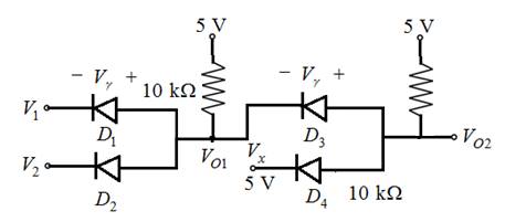
The given circuit is shown below.

Circuit diagram:

Logic “0” signal degrades as it goes through additional logic gates.
The diodes
Calculating the value of output voltage,
Calculating the value of output voltage,
Hence, output voltages are
Want to see more full solutions like this?
Chapter 2 Solutions
MICROELECT. CIRCUIT ANALYSIS&DESIGN (LL)


- A Three-phase, 12 pole, Y-connected alternator has 108 slots and 14 conductors per slot. The windings are (5/6 th) pitched. The flux per pole is 57 mWb distributed sinusoidally over the pole. If the machine runs at 500 r.p.m., determine the following: (a) The frequency of the generated e.m.f., (b) The distribution factor, (c) The pitch factor, and (d) The phase and line values of the generated e.m.f.?arrow_forwardTwo 3-ph, 6.6 kV, Y-connected, alternators supply a load of 3000 kW at 0.8 p.f. lagging. The synchronou impedance per phase of machine A is (0.5+110) and that of machine B is (0.4 +J12) . The excitation of machine A adjusted so that it delivers 150 A. The load is shared equally between the machines. Determine the armature curre p.f., induced e.m.f., and load angle of each machine?arrow_forwardName the circuit below? The output voltage is initially zero and the pulse width is 200 μs. Find the Vout and draw the output waveform? +2.5 V V 247 -2.5 V C 0.01 F Ri W 10 ΚΩarrow_forward
- Please work outarrow_forwardFind Vfinal when Vs up and Vs V. Which LED will light in each case? Red or Green? Justify your answers. Fill the table below. Vs 8 ΚΩ Vos Χρι + 3 ΚΩ www 6 ΚΩ ww 4 ΚΩ Yo www Vo Vec-12 V Nol V final Vm w 3 ΚΩ 5 V 38 ΚΩ R= 1 kQ V -12 V Red LED Green LED Vs Vo Vfinal Which LED is ON? Varrow_forwardCircuits help please solve and explain. Question in images providedarrow_forward
- + V 6.2 A 1.2 A S R 4 Ω Find the source voltage Vs 0.8 Aarrow_forwardDetermine i(t) for t≥ 0 given that the circuit below had been in steady state for a long time prior to t = 0. Also, I₁ = 1 5 A, R₁ =22, R2 =10 Q2, R3 = 32, R4 =7 2, and L=0.15 H. Also fill the table. m L ww R2 t = 0 R₁ 29 R3 R4 Time 0 iL(t) 0 8arrow_forwardPlease help explain this problemarrow_forward
- + P = 16 W w w P = 8 W I R₁ R2 E = RT=322 1- Determine R1, R2, E ΙΩarrow_forward+ 30 V = - 20 V + R 2- Use KVL to find the voltage V - V + + 8 Varrow_forwardFind the Thévenin equivalent circuit for the portions of the networks in Figure external to the elements between points a and b. a R₁ 2002 I = 0.1 A 0° Xc : 32 Ω R2 = 6802 20 Ω фъarrow_forward
