Videos
Find a couple of M.
Answer to Problem 16.142P
The couple of M=-7.19N.m.
Explanation of Solution
Given information:
The attached rod A mass is=0.8kg
And length is=160mm
Rod BP mass is=1kg
Length is=200mm
Explanation:
First consider the unit
So, we have to find the vertical distance from point P and point A(y)
Here, we take the coordinate points as (0,0.1m)
Then the position of the vector
Coordinate points of the point P with the point B is
Then the position vector is
Then the coordinate points with the point P and point E as (0,-0.16m)
Position vector is
Here, the unit vector k as angular direction in clockwise is negative and it is positive when counter clockwise.
Angular velocity of the rod BP in vector form is
Velocity of the rod BP is
Formulate the velocity equation of point P
Compare the i terms from equation (1) And (2)
Compare the equation (1) and (2) for j terms. We get,
So, the angular acceleration is zero.
Formulate the acceleration of the rod BP
Find the acceleration of the point P to the point E
Formulate the acceleration at the point P
Substitute the above values
Based on equations (3) and (4), we get,
Find the weight of the rod AE is get by
Then the moment of inertial of the rod AE is
Similarly, find the weight of the rod BP is
Then the moment of inertial of the rod BP
Here, the mass of the centers of rod AE and BP are to be considered as G and H.
Then the reference for point G with point A as (0,-0.08m).
Here the position vector is −(0.08m)j.
Similarly, the point H with point B as the reference as (-0.0866m,-0.05m). Position vector is −(0.0866m)i-(0.05m)j
Acceleration of the point G is
Find the acceleration at point H
Based on above figure, consider the moment about point B.
The magnitude of the couple applied on the rod is BP. It is considered as -7.19N.m and acts in a clockwise direction.
Find the force exerted on rod AE.
Answer to Problem 16.142P
The force exerted by rod AE is F=52.757N.
Explanation of Solution
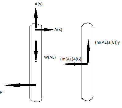
Considering the above diagram of free body of the rod AE
The force exerted by rod AE by block P is 52.75N. It is acted upon the left direction.
Want to see more full solutions like this?
Chapter 16 Solutions
VECTOR MECH...,DYNAMICS(LOOSE)-W/ACCESS


- (Read image)arrow_forwardUNIVERSIDAD NACIONAL DE SAN ANTONIO ABAD DEL CUSCO PRIMER EXAMEN PARCIAL DE MECÁNICA DE FLUIDOS I ............ Cusco, 23 de setiembre de 2024 AP. Y NOMBRES: ........ 1.- Para el tanque de la figura: a) Calcule la profundidad de la hidrolina si la profundidad del agua es de 2.8 m y el medidor del fondo del tanque da una lectura de 52.3kPa. b) Calcule la profundidad del agua si la profundidad de la hidrolina es 6.90 m y el medidor de la parte inferior del tanque registra una lectura de 125.3 kPa. Hidrolina Sp=0.90 Abertura Agua sup suge to but amulor quit y 2.- Calcule la magnitud de la fuerza resultante sobre el área A-B y la ubicación del centro de presión. Señale la fuerza resultante sobre el área y dimensione su ubicación con claridad. 3.5 ft 12 in: Oil (38-0.93) 14 in 8 inarrow_forwardplease solve this problem and give me the correct answer step by steparrow_forward
- reaction at a is 1.6 wL (pos) handwritten solutions only please. correct answers upvotedarrow_forward1 8 4 Add numbers so that the sum of any row or column equals .30 Use only these numbers: .1.2.3.4.5.6.10.11.12.12.13.14.14arrow_forwardUppgift 2 (9p) I77777 20 kN 10 kN/m 4 [m] 2 2 Bestäm tvärkrafts- och momentdiagram för balken i figuren ovan. Extrempunkter ska anges med både läge och värde i diagrammen.arrow_forward
- **Problem 8-45.** The man has a mass of 60 kg and the crate has a mass of 100 kg. If the coefficient of static friction between his shoes and the ground is \( \mu_s = 0.4 \) and between the crate and the ground is \( \mu_c = 0.3 \), determine if the man is able to move the crate using the rope-and-pulley system shown. **Diagram Explanation:** The diagram illustrates a scenario where a man is attempting to pull a crate using a rope-and-pulley system. The setup is as follows: - **Crate (C):** Positioned on the ground with a rope attached. - **Rope:** Connects the crate to a pulley system and extends to the man. - **Pulley on Tree:** The rope runs over a pulley mounted on a tree which redirects the rope. - **Angles:** - The rope between the crate and tree forms a \(30^\circ\) angle with the horizontal. - The rope between the tree and the man makes a \(45^\circ\) angle with the horizontal. - **Man (A):** Pulling on the rope with the intention of moving the crate. This arrangement tests the…arrow_forwardplease solve this problems follow what the question are asking to do please show me step by steparrow_forwardplease first write the line action find the forces and them solve the problem step by steparrow_forward
 Elements Of ElectromagneticsMechanical EngineeringISBN:9780190698614Author:Sadiku, Matthew N. O.Publisher:Oxford University Press
 Mechanics of Materials (10th Edition)Mechanical EngineeringISBN:9780134319650Author:Russell C. HibbelerPublisher:PEARSON
 Thermodynamics: An Engineering ApproachMechanical EngineeringISBN:9781259822674Author:Yunus A. Cengel Dr., Michael A. BolesPublisher:McGraw-Hill Education
 Control Systems EngineeringMechanical EngineeringISBN:9781118170519Author:Norman S. NisePublisher:WILEY
 Mechanics of Materials (MindTap Course List)Mechanical EngineeringISBN:9781337093347Author:Barry J. Goodno, James M. GerePublisher:Cengage Learning
 Engineering Mechanics: StaticsMechanical EngineeringISBN:9781118807330Author:James L. Meriam, L. G. Kraige, J. N. BoltonPublisher:WILEY