Concept explainers
Videos
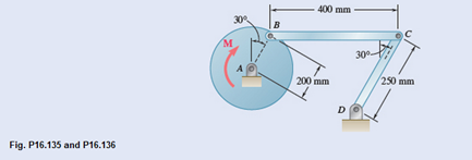
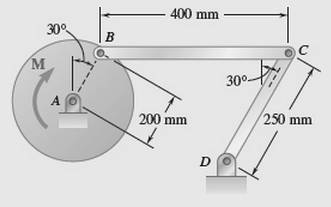
The 6-kg rod BC connects a 10-kg disk centered at A to a 5-kg rod CD. The motion of the system is controlled by the couple M applied to disk A. Knowing that at the instant shown disk A has an angular velocity of 36 rad/s clockwise and an angular acceleration of 150 rad/s2 counterclockwise determine (a) the couple M, (b) the components of the force exerted at C on rod BC.
(a)
The couple M applied at disk A.
Answer to Problem 16.136P
The couple M applied at disk A,
Explanation of Solution
Given information:
Radius of disk A, rAB=200mm.
Rod BC mass, m = 6kg.
Disk mass, m = 10kg.
Rod CD mass, m = 5kg.
Angular velocity of disk A,
Angular acceleration of the disk A,
A diagram is given with all dimensions,
Velocity of disk AB,
Disk radius,
Disk angular velocity,
Since point C velocity is parallel to point B velocity, the point C velocity magnitude and direction is same as point B
Rod CD angular velocity
Disk B acceleration,
Rod BC acceleration tangential component,
Rod BC acceleration,
Rod CD acceleration tangential component,
Rod CD acceleration,
Equation forces horizontal component from equations A and B,
Equation forces vertical component from equations A and B,
Acceleration of point A is zero since it is pivoted
Rod BC acceleration of mass centre P,
Rod CD acceleration of mass centre Q,
Disk AB effective force at mass centre,
Disk AB moment of inertia,
Rod BC effective force at mass centre,
Rod BC moment of inertia,
Rod CD effective force at mass centre,
Rod CD moment of inertia,
Rod BC free body diagram
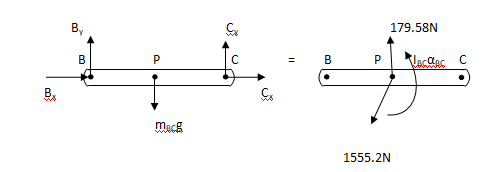
Figure A
Moment at point B from above figure,
Rod CD free body diagram
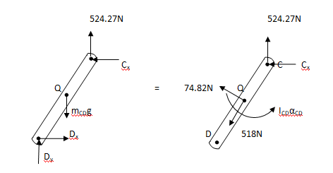
Figure B
Moment at point D from above figure,
Combined disk AB and rod BC free body diagram
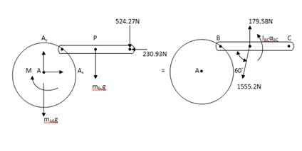
Figure C
From above figure, take moment at point A,
M is couple applied at point A
At disk A, couple applied magnitude is
Conclusion:
At disk A, couple applied magnitude is
(b)
Find the force components exerted on rod BC
Answer to Problem 16.136P
The force horizontal component exerted at point C is
Explanation of Solution
Given information:
Rod BC mass, m = 6kg
Disk mass, m = 10kg
Rod CD mass, m = 5kg
Rod BC free body diagram

Figure A
Moment at point B from above figure,
Rod CD free body diagram

Figure B
Moment at point D from above figure,
Conclusion:
The force horizontal component exerted at point C is
Want to see more full solutions like this?
Chapter 16 Solutions
VECTOR MECH...,DYNAMICS(LOOSE)-W/ACCESS


- My ID#016948724 please solve this problems and show me every step clear to follow pleasearrow_forwardMy ID# 016948724arrow_forwardPlease do not use any AI tools to solve this question. I need a fully manual, step-by-step solution with clear explanations, as if it were done by a human tutor. No AI-generated responses, please.arrow_forward
- Please do not use any AI tools to solve this question. I need a fully manual, step-by-step solution with clear explanations, as if it were done by a human tutor. No AI-generated responses, please.arrow_forwardPlease do not use any AI tools to solve this question. I need a fully manual, step-by-step solution with clear explanations, as if it were done by a human tutor. No AI-generated responses, please.arrow_forward[Q2]: The cost information supplied by the cost accountant is as follows:Sales 20,00 units, $ 10 per unitCalculate the (a/ newsale guantity and (b) new selling price to earn the sameVariable cost $ 6 per unit, Fixed Cost $ 30,000, Profit $ 50,000profit ifi) Variable cost increases by $ 2 per unitil) Fixed cost increase by $ 10,000Ili) Variable cost increase by $ 1 per unit and fixed cost reduces by $ 10,000arrow_forward
- can you please help me perform Visual Inspection and Fractography of the attatched image: Preliminary examination to identify the fracture origin, suspected fatigue striation, and corrosion evidences.arrow_forwardcan you please help[ me conduct Causal Analysis (FTA) on the scenario attatched: FTA diagram which is a fault tree analysis diagram will be used to gain an overview of the entire path of failure from root cause to the top event (i.e., the swing’s detachment) and to identify interactions between misuse, material decay and inspection errors.arrow_forwardhi can you please help me in finding the stress intensity factor using a k-calcluator for the scenario attathced in the images.arrow_forward
 Elements Of ElectromagneticsMechanical EngineeringISBN:9780190698614Author:Sadiku, Matthew N. O.Publisher:Oxford University Press
 Mechanics of Materials (10th Edition)Mechanical EngineeringISBN:9780134319650Author:Russell C. HibbelerPublisher:PEARSON
 Thermodynamics: An Engineering ApproachMechanical EngineeringISBN:9781259822674Author:Yunus A. Cengel Dr., Michael A. BolesPublisher:McGraw-Hill Education
 Control Systems EngineeringMechanical EngineeringISBN:9781118170519Author:Norman S. NisePublisher:WILEY
 Mechanics of Materials (MindTap Course List)Mechanical EngineeringISBN:9781337093347Author:Barry J. Goodno, James M. GerePublisher:Cengage Learning
 Engineering Mechanics: StaticsMechanical EngineeringISBN:9781118807330Author:James L. Meriam, L. G. Kraige, J. N. BoltonPublisher:WILEY