
Concept explainers
Videos
For the op−amp used in the inverting amplifier configuration in FigureP14.10, the open−loop parameters are
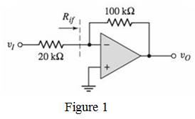
Figure P14.10
Want to see the full answer?
Check out a sample textbook solution
Chapter 14 Solutions
MICROELECT. CIRCUIT ANALYSIS&DESIGN (LL)


- A 3-phase, 4-wire distributor supplies a balanced voltage of 400/230 V to a load consisting of 50 A at p.f. 0-866 lagging for R-phase, 30 A at p.f. 0-866 leading for Y phase and 30 A at unity pf. for B phase. The resistance of each line conductor is 0-2 Q. The area of X-section of neutral is half of any line conductor: Calculate the supply end voltage for R phase. The phase sequence is RYB.arrow_forward- A 3-phase, 4-wire distributor supplies a balanced voltage of 400/230 V to a load consisting of 8 A at p.f. 0.7 lagging for R-phase, 10 A at p.f. 0-8 leading for Y phase and 12 A at unity p.f. for B phase. The resistance of each line conductor is 0.4 2. The reactance of neutral is 0.2 2. Calculate the neutral current, the supply voltage for R phase and draw the phasor diagram. The phase sequence is RYB.arrow_forwardNo AI WILL REJECTarrow_forward
- Please show all the steps!arrow_forward10-3) similar to Lathi & Ding, Prob. P.6.3-7 The Fourier transform P(f) of a the basic pulse p(t) used in a certain binary communication is shown in the figure below: P(f) 1 0.5 0 f₁ = 0.8 √₂ = 1.2 f, MHz (a) From the shape of P(f), explain at what pulse rate this pulse would satisfy Nyquist's first criterion. (b) Assuming that the pulse is a raised-cosine pulse, find its rolloff factor. (c) Find p(t) and verify that this pulse satisfies Nyquist's first criterion in the time domain. (d) Show how rapidly the pulse decays as a function of t, (i.e., what power of t does the envelope obey for large time values).arrow_forwardDon't use ai to answer I will report you answerarrow_forward
- Don't use ai to answer I will report you answerarrow_forwardDon't use ai to answer I will report you answerarrow_forwardChoose the correct answer for from the following sentences: 1. The purpose of the microprocessor is to control b. memory c. processing d. tasks a. switches 2. Which of the following instructions represents base-plus-index addressing mode? a. MOV AL,[BX] b. MOV AL,[SI] c. MOV AL,BX d. MOV AL,[BX+SI] 3. The BIU pre-fetches the instruction from memory and store them in b. memory c. stack d. queue a. register 4. Which function is used to control the PWM (Pulse Width Modulation) on the Arduino output pin? a. digitalRead() b. analogRead() c. digitalWrite() 5. Which port in the PIC16F877A has an 8 external interrupt inputs? a. Port-A b. Port-C c. Port-B d. analogWrite() d. Port-D d. 4KByte 6. How much Flash EEPROM memory program found in the PIC16F877A microcontroller? a. 32KByte b. 16KByte c. 8KBytearrow_forward
 Introductory Circuit Analysis (13th Edition)Electrical EngineeringISBN:9780133923605Author:Robert L. BoylestadPublisher:PEARSON
 Delmar's Standard Textbook Of ElectricityElectrical EngineeringISBN:9781337900348Author:Stephen L. HermanPublisher:Cengage Learning
 Programmable Logic ControllersElectrical EngineeringISBN:9780073373843Author:Frank D. PetruzellaPublisher:McGraw-Hill Education
 Fundamentals of Electric CircuitsElectrical EngineeringISBN:9780078028229Author:Charles K Alexander, Matthew SadikuPublisher:McGraw-Hill Education
 Electric Circuits. (11th Edition)Electrical EngineeringISBN:9780134746968Author:James W. Nilsson, Susan RiedelPublisher:PEARSON
 Engineering ElectromagneticsElectrical EngineeringISBN:9780078028151Author:Hayt, William H. (william Hart), Jr, BUCK, John A.Publisher:Mcgraw-hill Education,