
Concept explainers
Repeat Exercise 17 with Rw = 10 Ω, and verify your answers with an appropriate set of simulations if the operating frequency is 60 Hz.
Assume the system shown in Fig. 12.34 is balanced, Rw = 0, Van = 208∠0° V, and a positive phase sequence applies. Calculate all phase and line currents, and all phase and line voltages, if Zp is equal to (a) 1 kΩ; (b) 100 + j48 Ω; (c) 100 − j48 Ω.
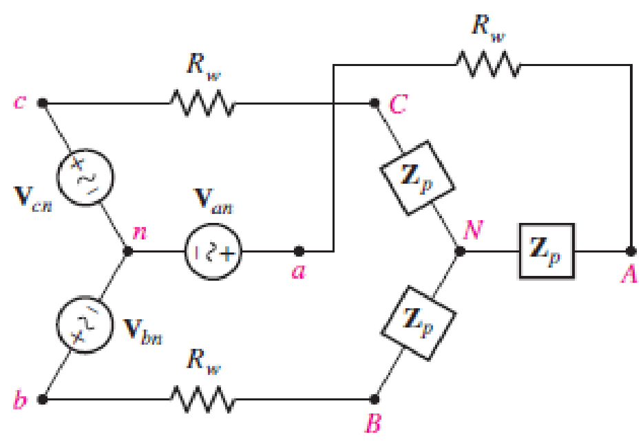
■ FIGURE 12.34
(a)
Find the line and phase currents, line and phase voltages at the load when the load impedance
Answer to Problem 18E
The line and phase currents are
Explanation of Solution
Given data:
The line resistance
The load impedance
The source phase voltage is
The simulation operation frequency is
LTspice Simulation:
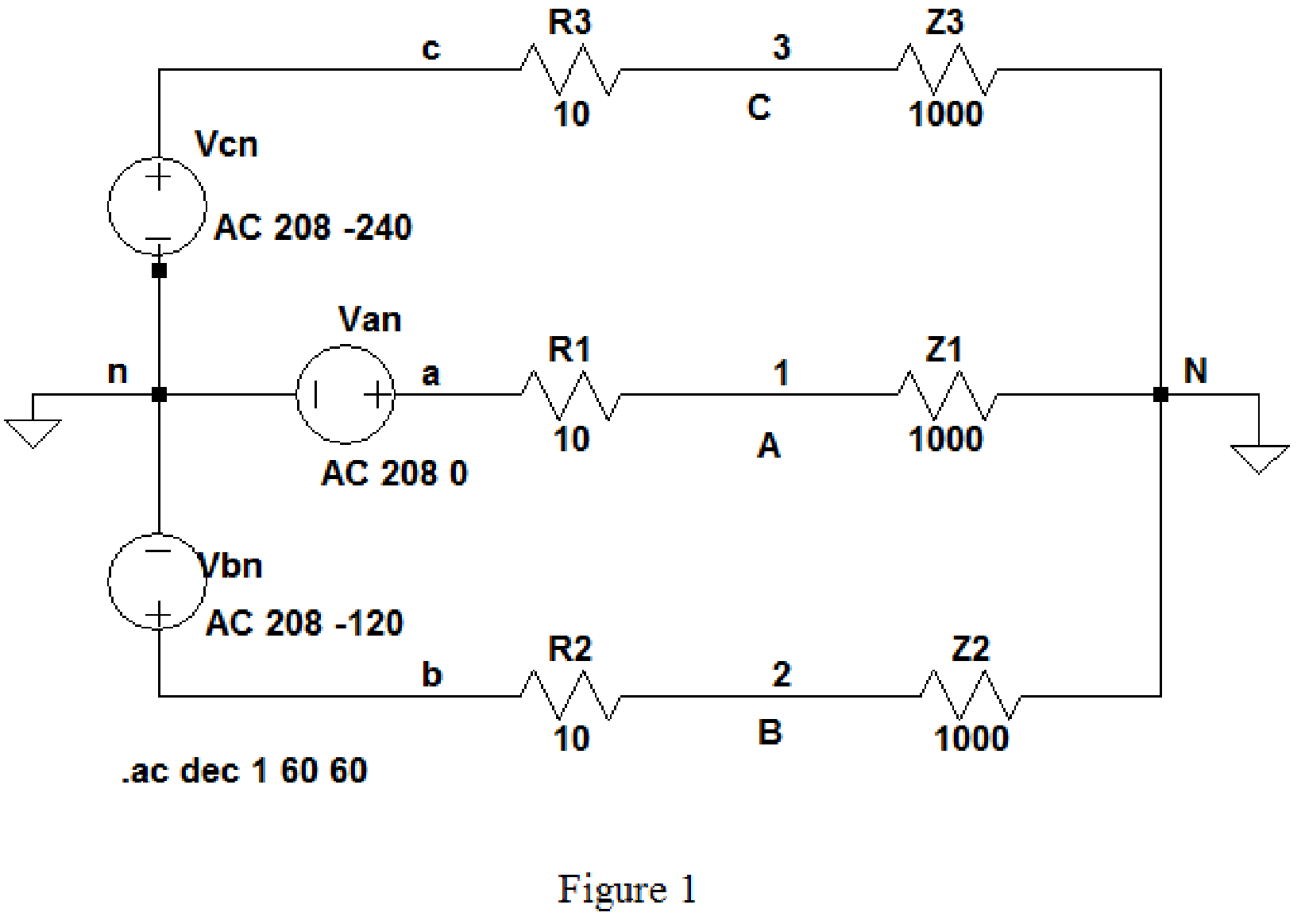
Draw the given circuit diagram as shown in Figure 1, where 1, 2, and 3 are placed for node representations using Label Net.
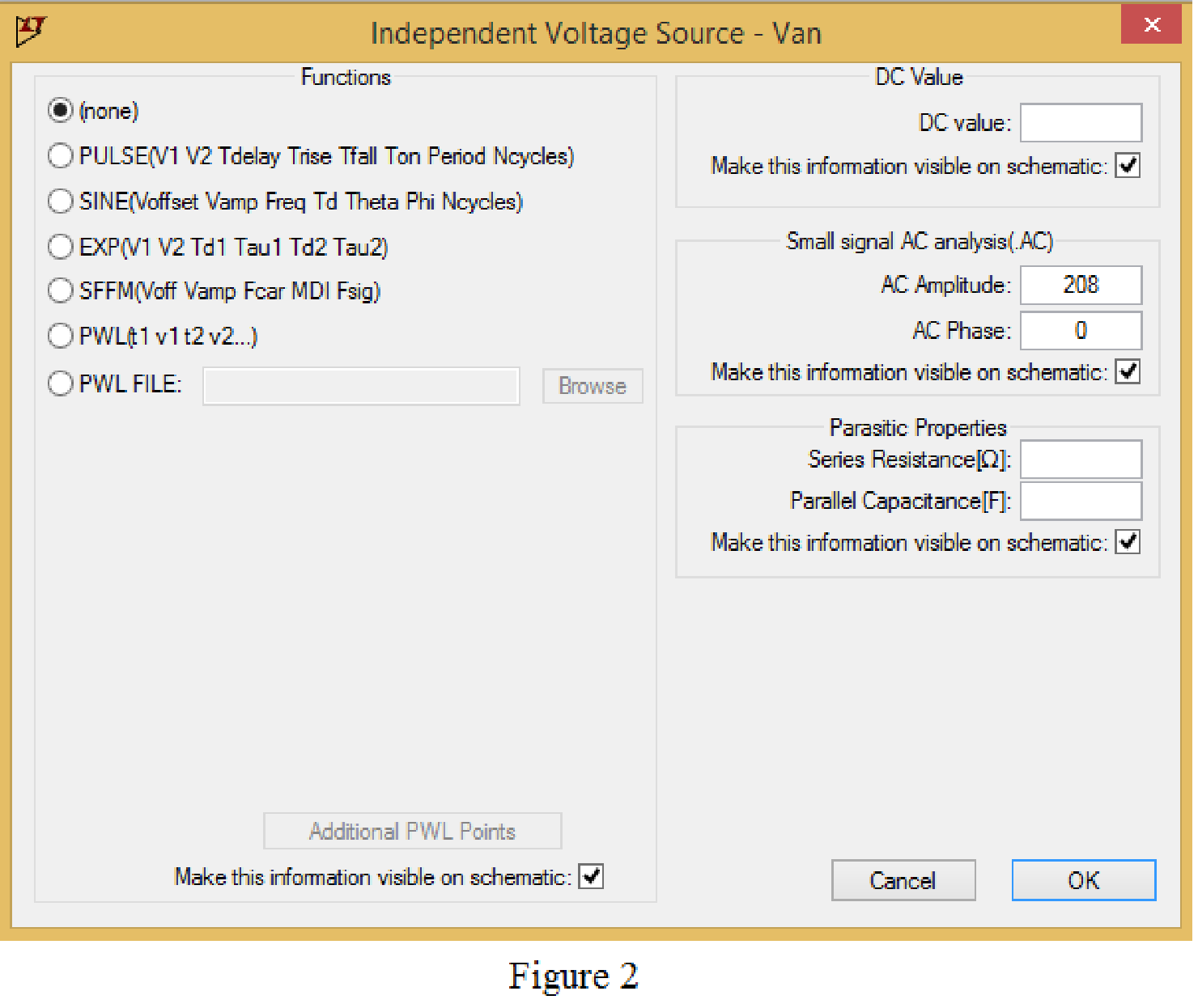
Set the values of voltages Van, Vbn and Vcn by right clicking on the voltage component, select none in “Functions” and enter the Small signal AC analysis parameters: AC amplitude as 208 and AC phase as 0 for V1, and enter other two voltage values accordingly positive phase sequence as shown in Figure 2 for V1.
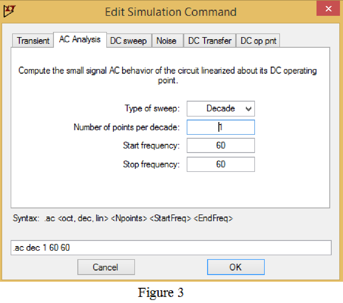
Now save the circuit, and open the “Edit Simulation command” choose AC analysis and select the sweep type as Decade, Number of points per decade 1, Start frequency and Stop frequency as 60 Hz shown in Figure 3.
Now, run the simulation for the designed circuit. The output for the AC analysis will displays as shown in Figure 4.
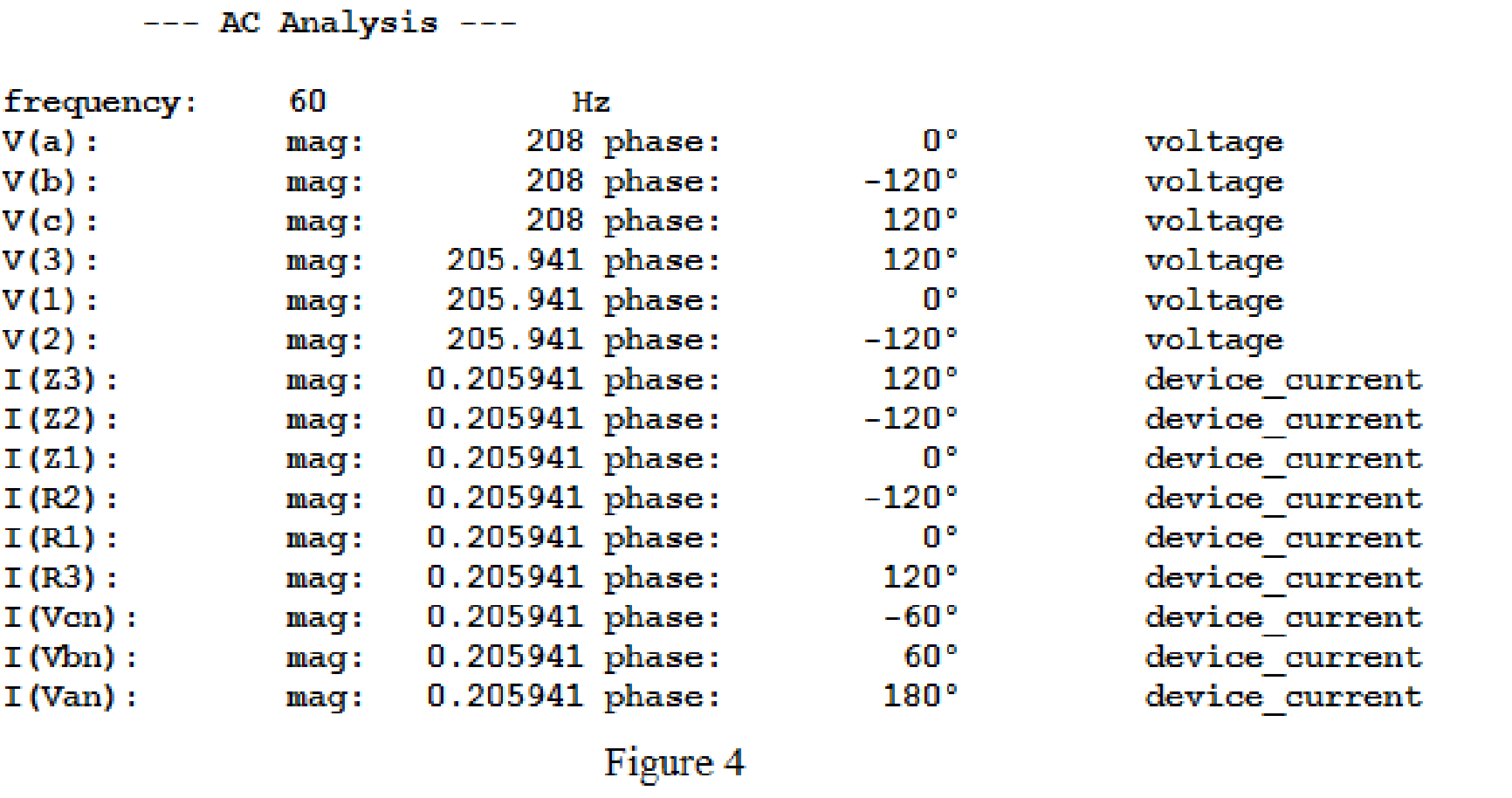
For the wye-wye connection, phase currents and line currents are equal and they are equals to
Then,
In above simulation results, the phase voltages at the load
Then, the phase voltages at the load are,
The magnitude of the phase voltages is
Write the formula to find the line voltage
Substitute
Write the formula to find the line voltage
Substitute
Write the formula to find the line voltage
Substitute
Conclusion:
Thus, the line and phase currents are
(b)
Find the line and phase currents, line and phase voltages at the load when the load impedance
Answer to Problem 18E
The line and phase currents are
The phase voltages are
Explanation of Solution
Given data:
Refer to part (a).
LTspice Simulation:
The load impedance is given as,
Where load resistance is
Write the formula to find the inductive reactance as follows.
Substitute
Draw the given circuit diagram as shown in Figure 5 for the load impedance
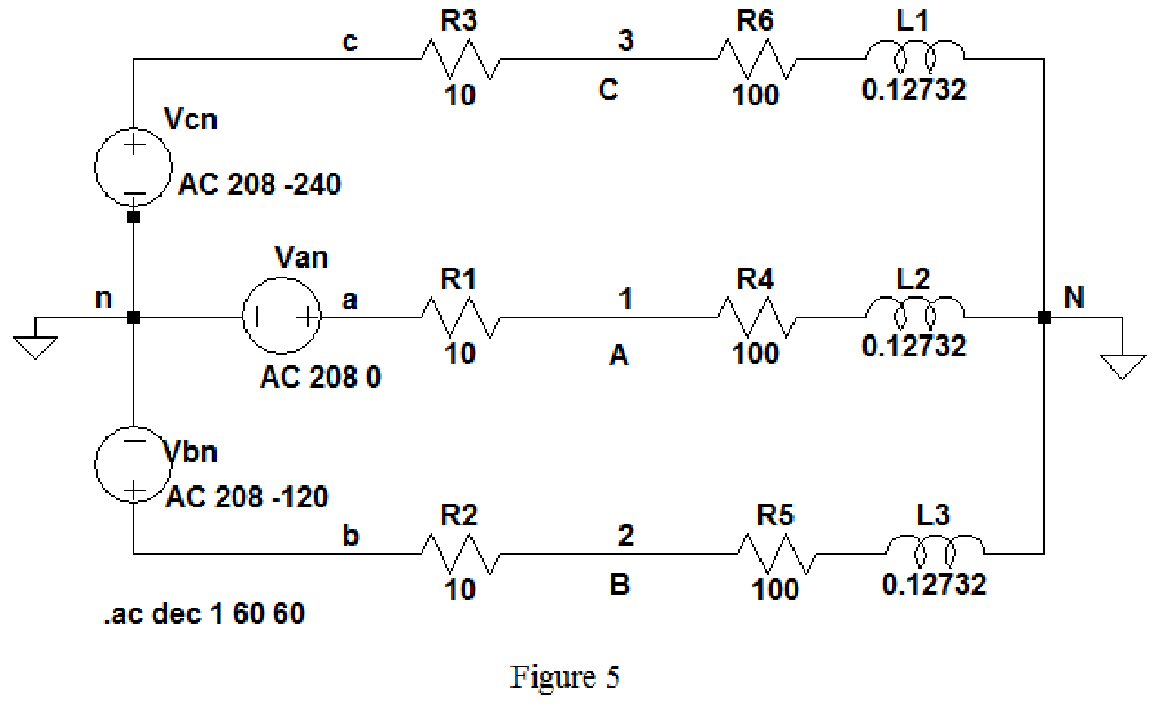
Keep the same simulation settings as given in Part(a) and run the simulation, then the output for the AC analysis will displays as shown in Figure 6.
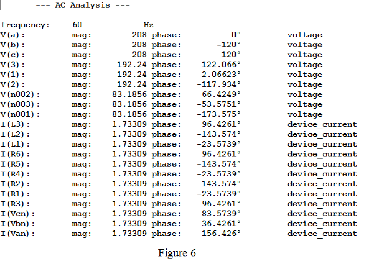
From above simulation results I(R1) or I(R4) or I(L1) is equals to
Then,
The phase voltages at the load
Then, the phase voltages at the load are,
The magnitude of the phase voltages is
Write the formula to find the line voltage
Substitute
Write the formula to find the line voltage
Substitute
Write the formula to find the line voltage
Substitute
Conclusion:
Thus, the line and phase currents are
The phase voltages are
(c)
Find the line and phase currents, line and phase voltages at the load when the load impedance
Answer to Problem 18E
The line and phase currents are
The phase voltages are
Explanation of Solution
Given data:
Refer to part (a).
LTspice Simulation:
The load impedance is given as,
Where load resistance is
Write the formula to find the inductive reactance as follows.
Substitute
Draw the given circuit diagram as shown in Figure 5 for the load impedance
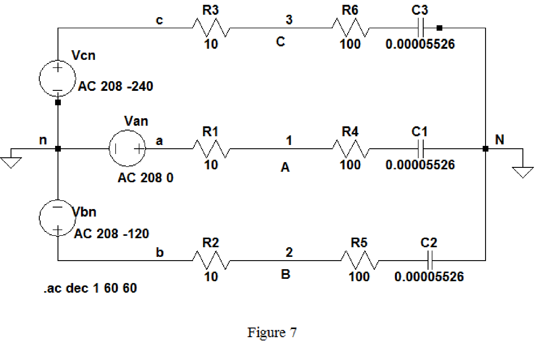
Keep the same simulation settings as given in part(a) and run the simulation, then the output for the AC analysis will displays as shown in Figure 8.
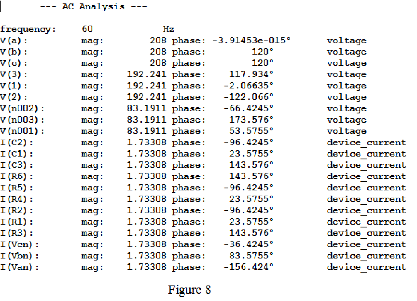
From above simulation results, since the phase currents and line currents are equal, I(R1) or I(R4) or I(C1) is equals to
Then,
The phase voltages at the load
Then, the phase voltages at the load are,
Use the same formula given in equation (1) to find the line voltage
Use the same formula given in equation (2) to find the line voltage
Use the same formula given in equation (3) to find the line voltage
Conclusion:
Thus, the line and phase currents are
The phase voltages are
Want to see more full solutions like this?
Chapter 12 Solutions
Loose Leaf for Engineering Circuit Analysis Format: Loose-leaf
- 6.7 The transmitting aerial shown in Fig. Q.3 is supplied with current at 80 A peak and at frequency 666.66 kHz. Calculate (a) the effective height of the aerial, and (b) the electric field strength produced at ground level 40 km away. 60 m Fig. Q.3 Input 48 m Eartharrow_forwardox SIM 12.11 Consider the class B output stage, using MOSFETs, shown in Fig. P12.11. Let the devices have |V|= 0.5 V and μC WIL = 2 mA/V². With a 10-kHz sine-wave input of 5-V peak and a high value of load resistance, what peak output would you expect? What fraction of the sine-wave period does the crossover interval represent? For what value of load resistor is the peak output voltage reduced to half the input? Figure P12.11 +5 V Q1 Q2 -5Varrow_forward4 H ་་་་་་་ 四一周 A H₂ Find out put c I writ R as a function G, H, Harrow_forward
- 4 H A H₂ 四一周 Find out put c I writ R as a function G, H, Harrow_forward8. (a) In a Round-Robin tournament, the Tigers beat the Blue Jays, the Tigers beat the Cardinals, the Tigers beat the Orioles, the Blue Jays beat the Cardinals, the Blue Jays beat the Orioles and the Cardinals beat the Orioles. Model this outcome with a directed graph. https://www.akubihar.com (b) (c) ✓ - Let G = (V, E) be a simple graph. Let R be the relation on V consisting of pairs of vertices (u, v) such that there is a path from u to vor such that u= v. Show that R is an equivalence relation. 3 3 Determine whether the following given pair of directed graphs, shown in Fig. 1 and Fig. 2, are isomorphic or not. Exhibit an isomorphism or provide a rigorous argument that none exists. 4+4=8 Աշ աշ ИНИЯ Fig. 1 Fig. 2 Querarrow_forwardEXAMPLE 4.5 Objective: Determine ID, circuit. V SG' SD Vs and the small - signal voltage gain of a PMOS transistor Consider the circuit shown in Figure 4.20(a). The transistor parameters are A K = 0.80m- V Р _2’TP = 0.5V, and λ = 0 Varrow_forward
 Introductory Circuit Analysis (13th Edition)Electrical EngineeringISBN:9780133923605Author:Robert L. BoylestadPublisher:PEARSON
 Delmar's Standard Textbook Of ElectricityElectrical EngineeringISBN:9781337900348Author:Stephen L. HermanPublisher:Cengage Learning
 Programmable Logic ControllersElectrical EngineeringISBN:9780073373843Author:Frank D. PetruzellaPublisher:McGraw-Hill Education
 Fundamentals of Electric CircuitsElectrical EngineeringISBN:9780078028229Author:Charles K Alexander, Matthew SadikuPublisher:McGraw-Hill Education
 Electric Circuits. (11th Edition)Electrical EngineeringISBN:9780134746968Author:James W. Nilsson, Susan RiedelPublisher:PEARSON
 Engineering ElectromagneticsElectrical EngineeringISBN:9780078028151Author:Hayt, William H. (william Hart), Jr, BUCK, John A.Publisher:Mcgraw-hill Education,


