
Concept explainers
Videos
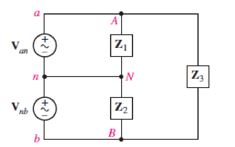
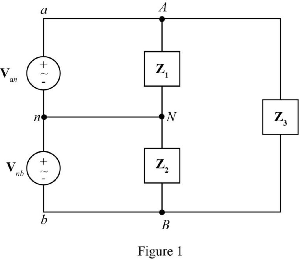
The single-phase three-wire system of Fig. 12.31 has three separate load impedances. If the source is balanced and Van = 110 +j0 V rms, (a) express Van and Vbn in phasor notation. (b) Determine the phasor voltage which appears across the impedance Z3. (c) Determine the average power delivered by the two sources if Z1 = 50 + j0 Ω, Z2 = 100 + j45 Ω, and Z3 = 100 – j90 Ω. (d) Represent load Z3 by a series connection of two elements, and state their respective values if the sources operate at 60 Hz.
(a)
The expression of phase to neutral voltage of phase
Answer to Problem 11E
The expression of phase to neutral voltage of phase
Explanation of Solution
Given data:
The phase to neutral voltage of phase
Calculation:
The given diagram is shown in Figure 1.
The general expression for the phasor notation is given by,
Here,
The magnitude of
Here,
The angle measured from the reference
Substitute
Substitute
Substitute
The voltage
The voltage
Substitute
Substitute
Conclusion:
Therefore, the expression of phase to neutral voltage of phase
(b)
The phasor voltage which appears across the impedance
Answer to Problem 11E
The phasor voltage which appears across the impedance
Explanation of Solution
Calculation:
The voltage across the impedance
The voltage across the impedance
The voltage across the impedance
The voltage across the impedance
Substitute
Conclusion:
Therefore, the phasor voltage which appears across the impedance
(c)
The average power delivered by the two sources.
Answer to Problem 11E
The average power delivered by source
Explanation of Solution
Given data:
The value of the impedance
The value of the impedance
The value of the impedance
Calculation:
The required diagram is shown in Figure 2.
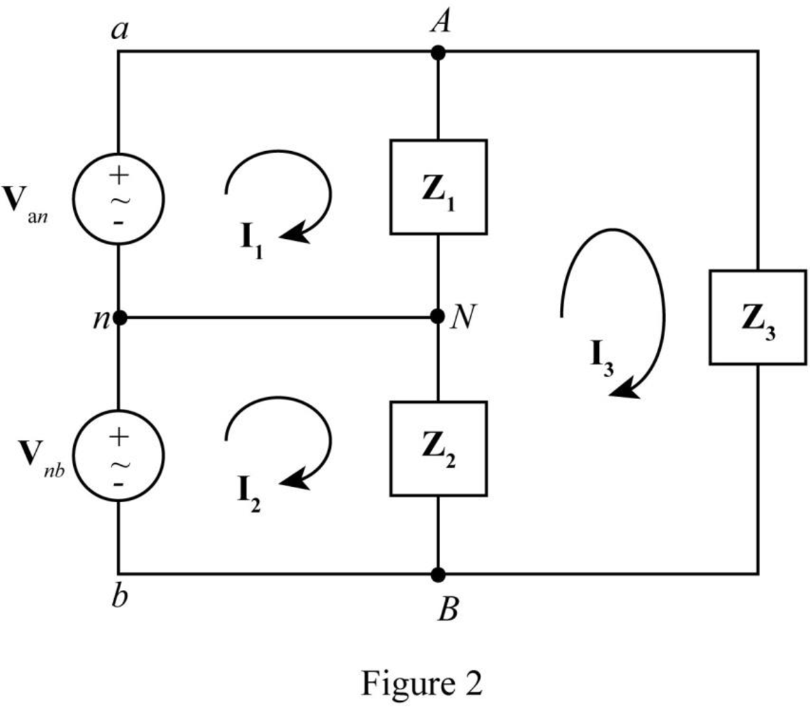
The formula to find current
Substitute
Substitute
Substitute
Substitute
The formula to find current
Substitute
Substitute
Substitute
Substitute
The formula to find current
Substitute
The power
Substitute
The power
Substitute
Conclusion:
Therefore, the average power delivered by source
(d)
The representation of load
Answer to Problem 11E
The impedance
Explanation of Solution
Given data:
The operating frequency is
Calculation:
The value of the impedance
The real part of
Hence, the resistance
The imaginary part of
Hence, The series capacitive reactance
Here,
Substitute
Conclusion:
Therefore, the impedance
Want to see more full solutions like this?
Chapter 12 Solutions
Loose Leaf for Engineering Circuit Analysis Format: Loose-leaf


- A conductor 300 mm long carries a current of 13A and is at right-angles to a magnetic fieldbetween two circular pole faces, each of diameter 80 mm. If the total flux between the polefaces is 0.75 mWb, calculate the force exerted on the conductor. [ANS = 0.582 N]arrow_forwarda) find Rthb) Find Vth in the circuit c)Draw the Thevenin Equivalent of the circuit to tge left of the a and b terminalsarrow_forwardAn electric car runs on batteries, but needs to make constant stops to re-charge. If a trailer is attached to the car that carries a generator, and the generator is turned by a belt attached to the wheels of the trailer, will the car be able to drive forever without stopping?arrow_forward
- A singl core cable of voltage 30 kv. The diameter of Conductor is 3 cm. The diameter of cable is 25 cm. This cable has Two layer of insulator having arelative permittivity 5-3 respectively of The ratio of maximum electric stress of maximum electric stress 8 First layer to the of second layer is 10 Find & 1- The thickness of each layers. 3- The voltage of each layers. §. Layers The saving in radius of cable if another ungrading cable has the Same maximum electric stress, Total village, Conductor diameter of grading cable.arrow_forward66 KV sing care Cable has a drameter of conductor of 3 cm. The radius of cable is 10 cm. This Cable house Two relative permmitivity of insulation 6 and 4 respectively. If The ratio of maximum electric stress of first layer to the maximum eledric streep & second layer is s 1- find the village & each layers. 2- Min- electric stress J Cable 3- Compare the voltage of ungrading Cable has the same distance and relectric stresses.arrow_forwardPrelab Information 1. Laboratory Preliminary Discussion First-order Low-pass RC Filter Analysis The first-order low-pass RC filter shown in figure 1 below represents all voltages and currents in the time domain. It is of course possible to solve for all circuit voltages using time domain differential equation techniques, but it is more efficient to convert the circuit to its s-domain equivalent as shown in figure 2 and apply Laplace transform techniques. vs(t) i₁(t) + R₁ ww V₁(t) 12(t) Lic(t) Vout(t) = V2(t) R₂ Vc(t) C Vc(t) VR2(t) = V2(t) + Vs(s) Figure 1: A first-order low-pass RC filter represented in the time domain. I₁(s) R1 W + V₁(s) V₂(s) 12(s) Ic(s) + Vout(S) == Vc(s) Vc(s) Zc(s) = = VR2(S) V2(s) Figure 2: A first-order low-pass RC filter represented in the s-domain.arrow_forward
- Solve it in a different way than the previous solution that I searched forarrow_forwardA lossless uncharged transmission line of length L = 0.45 cm has a characteristic impedance of 60 ohms. It is driven by an ideal voltage generator producing a pulse of amplitude 10V and width 2 nS. If the transmission line is connected to a load of 200 ohms, sketch the voltage at the load as a function of time for the interval 0 < t < 20 nS. You may assume that the propagation velocity of the transmission is c/2. Answered now answer number 2. Repeat Q.1 but now assume the width of the pulse produced by the generator is 4 nS. Sketch the voltage at the load as a function of time for 0 < t < 20 nS.arrow_forwardSolve this experiment with an accurate solution, please. Thank you.arrow_forward
 Power System Analysis and Design (MindTap Course ...Electrical EngineeringISBN:9781305632134Author:J. Duncan Glover, Thomas Overbye, Mulukutla S. SarmaPublisher:Cengage Learning