
Loose Leaf for Engineering Circuit Analysis Format: Loose-leaf
9th Edition
ISBN: 9781259989452
Author: Hayt
Publisher: Mcgraw Hill Publishers
expand_more
expand_more
format_list_bulleted
Concept explainers
Videos
Textbook Question
Chapter 12, Problem 43E
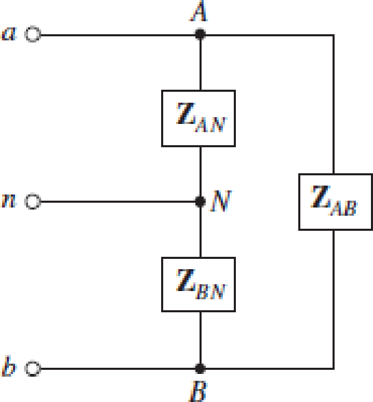
(a) Is the load represented in Fig. 12.41 considered a three-phase load? Explain. (b) If ZAN = 1 − j7 Ω,  and ZAB = 2 + j Ω, calculate all phase (and line) currents and voltages assuming a phase to neutral voltage of 120 VAC (the two phases are 180° out of phase). (c) Under what circumstances does current flow in the neutral wire?
FIGURE 12.41
Expert Solution & Answer
Want to see the full answer?
Check out a sample textbook solution
Students have asked these similar questions
Can you solve the following problem and show how the answer was found:
A17)
Using Carson's rule, determine the transmission bandwidth for commercial FM radio broadcasting, provided that the maximum value of frequency deviation is 75 kHz and the bandwidth of the audio signal is 15 kHz
Chapter 12 Solutions
Loose Leaf for Engineering Circuit Analysis Format: Loose-leaf
Ch. 12.1 - Let and . Find (a) Vad; (b) Vbc; (c) Vcd.Ch. 12.2 - Prob. 2PCh. 12.2 - Modify Fig. 12.9 by adding a 1.5 resistance to...Ch. 12.3 - A balanced three-phase three-wire system has a...Ch. 12.3 - A balanced three-phase three-wire system has a...Ch. 12.3 - Three balanced Y-connected loads are installed on...Ch. 12.4 - Each phase of a balanced three-phase -connected...Ch. 12.4 - Prob. 8PCh. 12.5 - Determine the wattmeter reading in Fig. 12.24,...Ch. 12.5 - Prob. 10P
Ch. 12 - Prob. 1ECh. 12 - Prob. 2ECh. 12 - Prob. 3ECh. 12 - Describe what is meant by a polyphase source,...Ch. 12 - Prob. 5ECh. 12 - Prob. 6ECh. 12 - Prob. 7ECh. 12 - Prob. 8ECh. 12 - Prob. 9ECh. 12 - Prob. 10ECh. 12 - The single-phase three-wire system of Fig. 12.31...Ch. 12 - Prob. 12ECh. 12 - Referring to the balanced load represented in Fig....Ch. 12 - Prob. 14ECh. 12 - Prob. 15ECh. 12 - Consider a simple positive phase sequence,...Ch. 12 - Assume the system shown in Fig. 12.34 is balanced,...Ch. 12 - Repeat Exercise 17 with Rw = 10 , and verify your...Ch. 12 - Prob. 19ECh. 12 - Prob. 20ECh. 12 - Prob. 21ECh. 12 - Prob. 22ECh. 12 - A three-phase system is constructed from a...Ch. 12 - Prob. 24ECh. 12 - Each load in the circuit of Fig. 12.34 is composed...Ch. 12 - Prob. 26ECh. 12 - Prob. 27ECh. 12 - A three-phase load is to be powered by a...Ch. 12 - For the two situations described in Exercise 28,...Ch. 12 - Prob. 30ECh. 12 - Prob. 31ECh. 12 - Prob. 32ECh. 12 - Repeat Exercise 32 if Rw = 1 . Verify your...Ch. 12 - Prob. 34ECh. 12 - Prob. 35ECh. 12 - Prob. 36ECh. 12 - A wattmeter is connected into the circuit of Fig....Ch. 12 - Find the reading of the wattmeter connected in the...Ch. 12 - (a) Find both wattmeter readings in Fig. 12.39 if...Ch. 12 - Circuit values for Fig. 12.40 are , , , , . Find...Ch. 12 - Prob. 41ECh. 12 - Prob. 42ECh. 12 - (a) Is the load represented in Fig. 12.41...Ch. 12 - Prob. 44E
Knowledge Booster


Learn more about
Need a deep-dive on the concept behind this application? Look no further. Learn more about this topic, electrical-engineering and related others by exploring similar questions and additional content below.Similar questions
- 2. Laboratory Preliminary Discussion First-order High-pass RC Filter Analysis The first-order high-pass RC filter shown in figure 3 below represents all voltages and currents in the time domain. We will again convert the circuit to its s-domain equivalent as shown in figure 4 and apply Laplace transform techniques. ic(t) C vs(t) i₁(t) + + vc(t) R1 ww Vi(t) || 12(t) V2(t) R₂ Vout(t) VR2(t) = V2(t) Figure 3: A first-order high-pass RC filter represented in the time domain. Ic(s) C + Vs(s) I₁(s) + + Vc(s) R₁ www V₁(s) 12(s) V₂(s) R₂ Vout(S) = VR2(S) = V2(s) Figure 4: A first-order high-pass RC filter represented in the s-domain. Again, to generate the s-domain expression for the output voltage, You (S) = V2 (s), for the circuit shown in figure 4 above, we can apply voltage division in the s-domain as shown in equation 2 below. Equation 2 will be used in the prelab computations to find an expression for the output voltage, xc(t), in the time domain. equation (2) R₂ Vout(s) = V₂(s) = R₂+…arrow_forwardCan you show me the steps to get the last part after the second equal sign.arrow_forwardPrelab Information 1. Laboratory Preliminary Discussion First-order Low-pass RC Filter Analysis The first-order low-pass RC filter shown in figure 1 below represents all voltages and currents in the time domain. It is of course possible to solve for all circuit voltages using time domain differential equation techniques, but it is more efficient to convert the circuit to its s-domain equivalent as shown in figure 2 and apply Laplace transform techniques. vs(t) i₁(t) + R₁ ww V₁(t) 12(t) Lic(t) Vout(t) = V2(t) R₂ Vc(t) C Vc(t) VR2(t) = V2(t) + Vs(s) Figure 1: A first-order low-pass RC filter represented in the time domain. I₁(s) R1 W + V₁(s) V₂(s) 12(s) Ic(s) + Vout(S) == Vc(s) Vc(s) Zc(s) = = VR2(S) V2(s) Figure 2: A first-order low-pass RC filter represented in the s-domain.arrow_forward
- A.15 Consider a communication channel, transfer characteristic of which is defined by the nonlinear relation, y(t) = x(t) + x² (t), where x(t) is the input and y(t) is the output. Assuming the input is an FM signal, x(t) = cos (2лft+(t)), find y(t). Is it possible to retrieve x(t) from y(t)? If so, how?arrow_forward1) Show that a regenerative receiver can be used to recover message from the following modulated signals. a. DSB-PC b. DSB-SC 1b) Does the receiver need to recover the carrier phase? 1c) What are the filtering requirements and restrictions on message signal bandwidth and carrier frequency.arrow_forward2) Estimate the transmission bandwidth for the following FM modulated signals (W is the message bandwidth) a) W1KHz and frequency deviation of 75KHz b) W = 20KHz and frequency deviation of 75KHz c) W1KHz and frequency deviation of 150KHz d) W20KHz and frequency deviation of 150KHZarrow_forward
- I want to explain how the result becomes (735.1) Hz) and what are the steps and explain the reasons? Q6 The FET shown in Fig. 1.43 has gm = 3.4mS and ra =100 K. Find the approximate lower cutoff frequency. Ans: 735.1 Hz. 25V 2ΚΩ 1.5ΜΩ 0.02µF 0.02µF 20 ΚΩ 330kQ 820 ΩΣ OpF Fig. 1.43 Circuit for Q6. 40ΚΩarrow_forward3. What is the function of LM565 pin 6? 4. What is the purpose of the multistage low-pass filter between the LM565 output and the comparator input? C10.1μ FSK Input w₁ R2 100k -o+5V(Vcc) VR1 10k C4 C5: 0.1 μ. 0.1μ 0.1 μ 8 10 R3 R4 D₁ FSK Phase Rx 7 10K 10K Detector www ww ww 1N4004 + Demodulated Output 6 AMP R₁ 6 100k 3 C₂ 0.05 μ VCO 4 5 9 U1 -5V LM565 -0-5V(VEE) Fig. 14-2 FSK demodulator U2 R6 μ4741 10karrow_forward1. What components determine the free-running frequency of the VCO in LM565 of Fig. 14-2? 2. What is the purpose of μA741 in Fig. 14-2? C10.1μ FSK Input -o+5V(Vcc) VR1 10k C4 C5: 0.1 μ. 0.1 μ 0.1 μ 8 10 R3 R4 R5 Phase Rx 7 10K 10K 10k D₁ FSK Detector www ww ww ww 1N4004 + Demodulated Output AMP 6 R₁ 6 100k w₁ R2 100k 3 C₂ 0.05 μ VCO 4 5 9 U1 -5V LM565 -0-5V(VEE) Fig. 14-2 FSK demodulator U2 R6 μ4741 10karrow_forward
- When troubleshooting power and control circuits, approximate meter readings should be anticipated if the meter readings are going to be used to help determine circuit problems. Determine the expected DMM reading if the ciircuit is working properly. The expected reading of DMM 1 with the motor on is what VAC? And the expected reading of DMM 2 with the motor is on is what VAC? And The expected reading of DMM 3 with the motor on is What mA?arrow_forwardDU 1. Describe the operations of Q1, Q2 and LM566. 2. Describe the functions of VR1 and VR2. R6 lk R3 BRUD 3. If the input frequency is higher than the FSK frequency, does the FSK modulator operate normally? 0+12V R10 5.6k 6 10k VRI 500k U₁ LM566 3 VCO output 7 Digital input R₁ VR2 10k ww 1k Qi C945 C945 C5 I 0.1 uF C6 luF C₁ 0.01μ R2 10k ww R$ 100k C3 +12V 0.01μ R9 100k +12V 6 R710k Rs 100k 6 R4 100k P FSK output ww ww + www + 3 3 4 U U₂ 1000p -12V HA741 1000p-12V µА741 Fig. 13-2 FSK modulator CTS circuit.arrow_forward. 30-dB, right-circularly polarized antenna in a radio link radiates 5-W of power t 2 GHz. The input impedance of this antenna is 75 ohms, and it is attached ɔ a 50-ohm transmission line. The receiving antenna has an impedance mismatch at its terminals, - which leads to a VSWR of 2. The receiving antenna is about 95% efficient and has a field pattern near the beam maximum given by E, = (2âx + jây) F, (0, 0). The distance between the two antennas is 4,000 km, and the receiving antenna Directivity is 100. Determine the Minimum power Delivered to receiving antenna. 1arrow_forward
arrow_back_ios
SEE MORE QUESTIONS
arrow_forward_ios
Recommended textbooks for you
 Power System Analysis and Design (MindTap Course ...Electrical EngineeringISBN:9781305632134Author:J. Duncan Glover, Thomas Overbye, Mulukutla S. SarmaPublisher:Cengage Learning
Power System Analysis and Design (MindTap Course ...
Electrical Engineering
ISBN:9781305632134
Author:J. Duncan Glover, Thomas Overbye, Mulukutla S. Sarma
Publisher:Cengage Learning
What is the Difference Between Single Phase and Three Phase???; Author: Electrician U;https://www.youtube.com/watch?v=FEydcr4wJw0;License: Standard Youtube License