
Videos
Consider a two-stage cascade refrigeration cycle with a flash chamber as shown in the figure with refrigerant-134a as the working fluid. The evaporator temperature is −10°C and the condenser pressure is 1600 kPa. The refrigerant leaves the condenser as a saturated liquid and is throttled to a flash chamber operating at 0.45 MPa. Part of the refrigerant evaporates during this flashing process, and this vapor is mixed with the refrigerant leaving the low-pressure compressor. The mixture is then compressed to the condenser pressure by the high-pressure compressor. The liquid in the flash chamber is throttled to the evaporator pressure and cools the refrigerated space as it vaporizes in the evaporator. The mass flow rate of the refrigerant through the low-pressure compressor is 0.11 kg/s. Assuming the refrigerant leaves the evaporator as a saturated vapor and the isentropic efficiency is 86 percent for both compressors, determine (a) the mass flow rate of the refrigerant through the high-pressure compressor, (b) the rate of refrigeration supplied by the system, and (c) the COP of this refrigerator. Also, determine (d) the rate of refrigeration and the COP if this refrigerator operated on a single-stage vapor-compression cycle between the same evaporating temperature and condenser pressure with the same compressor efficiency and the same flow rate as calculated in part a.
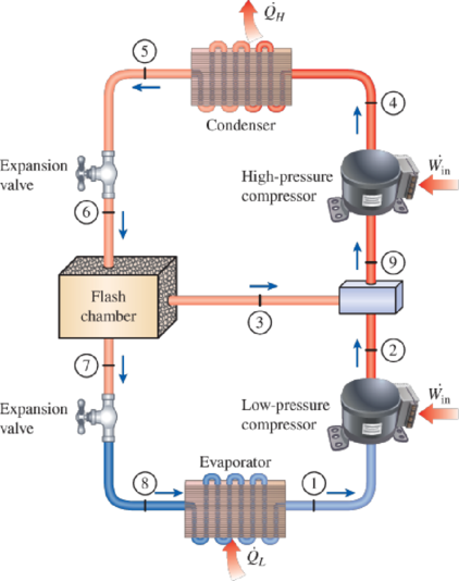
FIGURE P11–65
(a)
The mass flow rate of the refrigerant through the high-pressure compressor.
Answer to Problem 65P
The mass flow rate of the refrigerant through the high-pressure compressor is
Explanation of Solution
Show the T-s diagram as in Figure (1).
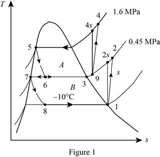
From Figure (1), write the specific enthalpy at state 6 is equal to state 5 due to throttling process.
Here, specific enthalpy at state 6 and 5 is
From Figure (1), write the specific enthalpy at state 8 is equal to state 7 due to throttling process.
Here, specific enthalpy at state 8 and 7 is
Express enthalpy at state 1.
Here, enthalpy saturation vapor at temperature of
Express entropy at state 1.
Here, entropy saturation vapor at temperature of
Express the specific enthalpy at state 2.
Here, specific enthalpy at state 2s is
Express enthalpy at state 3.
Here, enthalpy saturation vapor at pressure of
Express enthalpy at state 5.
Here, enthalpy saturation liquid at pressure of
Express enthalpy at state 7.
Here, enthalpy saturation liquid at pressure of
Express the quality at state 6.
Express the mass flow rate of the refrigerant.
Here, mass flow rate at state 7 is
Conclusion:
Refer Table A-11, “saturated refrigerant-134a-temperature table”, and write enthalpy saturation vapor at temperature of
Substitute
Refer Table A-11, “saturated refrigerant-134a-temperature table”, and write entropy saturation vapor at temperature of
Substitute
Perform the unit conversion of pressure at state 2 from
Refer Table A-13, “superheated refrigerant 134a”, and write the specific enthalpy at state 2s corresponding to pressure at state 2 of
Here, enthalpy at state 2s is
Substitute
Refer Table A-12, “saturated refrigerant-134a-pressure table”, and write the enthalpy saturation vapor at pressure of
Substitute
Refer Table A-12, “saturated refrigerant-134a-pressure table”, and write the enthalpy saturation liquid at pressure of
Substitute
Substitute
Refer Table A-12, “saturated refrigerant-134a-pressure table”, and write the enthalpy saturation liquid at pressure of
Substitute
Substitute
Substitute
Substitute
Hence, the mass flow rate of the refrigerant through the high-pressure compressor is
(b)
The rate of refrigeration supplied by the system.
Answer to Problem 65P
The rate of refrigeration supplied by the system is
Explanation of Solution
Express the mass flow rate at state 3.
Express the enthalpy at state 9.
Express the enthalpy at state 4.
Here, specific enthalpy at state 4s is
Express the rate of heat removal from the refrigerated space.
Conclusion:
Substitute
Substitute
Refer Table A-13, “superheated refrigerant 134a”, and write the specific enthalpy at state 9 corresponding to pressure at state 9 of
Here, entropy at state 9 is
Refer Table A-13, “superheated refrigerant 134a”, and write the specific enthalpy at state 4s corresponding to pressure at state 4 of
Write the formula of interpolation method of two variables.
Here, the variables denote by x and y is specific entropy at state 9 and specific enthalpy at state 4s respectively.
Show the specific enthalpy at state 4s corresponding to specific entropy as in Table (1).
|
Specific entropy at state 9 |
Specific enthalpy at state 4s |
| 0.9164 | 280.71 |
| 0.9399 | |
| 0.9536 | 293.27 |
Substitute
Thus, the specific enthalpy at state 4s is,
Substitute
Substitute
Hence, the rate of refrigeration supplied by the system is
(c)
The COP of the refrigerator.
Answer to Problem 65P
The COP of the refrigerator is
Explanation of Solution
Express the power input.
Express the coefficient of performance.
Conclusion:
Substitute
Substitute
Hence, the coefficient of performance of the refrigerator is
(d)
The rate of refrigeration and the COP of the refrigerator.
Answer to Problem 65P
The rate of refrigeration is
Explanation of Solution
Show the T-s diagram as in Figure (1).
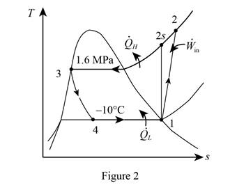
From Figure (1), write the specific enthalpy at state 4 is equal to state 3 due to throttling process.
Here, specific enthalpy at state 4 and 3 is
Express the enthalpy at state 2.
Here, specific enthalpy at state 2s is
Express enthalpy at state 3.
Here, enthalpy saturation vapor at pressure of
Express the rate of refrigeration.
Express the rate of work input.
Express the coefficient of performance.
Conclusion:
Refer Table A-13, “superheated refrigerant 134a”, and write the specific enthalpy at state 2s corresponding to pressure at state 2 of
Show the specific enthalpy at state 2s corresponding to specific entropy as in Table (2).
|
Specific entropy at state 2 |
Specific enthalpy at state 2s |
| 0.9164 | 280.71 |
| 0.9378 | |
| 0.9536 | 293.27 |
Use excels and tabulates the values from Table (2) in Equation (XV) to get,
Thus, the specific enthalpy at state 2s is,
Substitute
Refer Table A-12, “saturated refrigerant-134a-pressure table”, and write the enthalpy saturation liquid at pressure of
Substitute
Substitute
Substitute
Hence, the rate of refrigeration is
Substitute
Substitute
Hence, the coefficient of performance of the refrigerator is
Want to see more full solutions like this?
Chapter 11 Solutions
THERMODYNAMICS (LL)-W/ACCESS >CUSTOM<


- A garden hose attached with a nozzle is used to fill a 20-gal bucket. The inner diameter of the hose is 1 in and it reduces to 0.53 in at the nozzle exit. The average velocity in the hose is 8 ft/s and the density of water is 62.4 lbm/ft3. NOTE: This is a multi-part question. Once an answer is submitted, you will be unable to return to this part. Determine the volume and mass flow rates of water through the hose. The volume flow rate of water through the hose is ft3/s. The mass flow rate of water through the hose is lbm/s. The change in time? What is the exit velocity?arrow_forwardA 23-ft3 rigid tank initially contains saturated refrigerant-134a vapor at 160 psia. As a result of heat transfer from the refrigerant, the pressure drops to 50 psia. NOTE: This is a multi-part question. Once an answer is submitted, you will be unable to return to this part. Determine the final temperature. Use data from refrigerant tables. The final temperature is ºF.arrow_forwardA 23-ft3 rigid tank initially contains saturated refrigerant-134a vapor at 160 psia. As a result of heat transfer from the refrigerant, the pressure drops to 50 psia. NOTE: This is a multi-part question. Once an answer is submitted, you will be unable to return to this part. Determine the heat transfer. The heat transfer is Btu.arrow_forward
- The shaft shown in the figure below is subjected to axial loads as illustrated. The diameters of segments AB, BC, and CD are 20mm, 25mm, and 15mm, respectively. If the modulus of elasticity of the material is 610 MPa. Determine the change of A to D lengtharrow_forwardDetermine the final pressure and temperature. The final pressure is kPa. The final temperature is ºC.arrow_forwardAir enters the 1-m2 inlet of an aircraft engine at 100 kPa and 20°C with a velocity of 184 m/s. Determine the volume flow rate, in m3/s, at the engine’s inlet and the mass flow rate, in kg/s, at the engine’s exit. The gas constant of air is R = 0.287 kPa·m3/kg·K. The volume flow rate at the engine’s inlet m3/s. The mass flow rate at the engine’s exit is kg/s.arrow_forward
- The ventilating fan of the bathroom of a building has a volume flow rate of 33 L/s and runs continuously. If the density of air inside is 1.20 kg/m3, determine the mass of air vented out in one day. The mass of air is kg.arrow_forwardA steady-flow compressor is used to compress helium from 15 psia and 70°F at the inlet to 200 psia and 600°F at the outlet. The outlet area and velocity are 0.01 ft2 and 100 ft/s, respectively, and the inlet velocity is 53 ft/s. Determine the mass flow rate and the inlet area. The gas constant of helium is R = 2.6809 psia·ft3/lbm·R. The mass flow rate is lbm/s. The inlet area is ft2.arrow_forward1. The maximum and minimum stresses as well as the shear stress seen subjected the piece in plane A-A. Assume it is a cylinder with a diameter of 12.7mm 2. Draw the Mohr circle for the stress state using software. 3. Selection of the material for the prosthesis, which must be analyzed from the point of safety and cost view.arrow_forward
 Refrigeration and Air Conditioning Technology (Mi...Mechanical EngineeringISBN:9781305578296Author:John Tomczyk, Eugene Silberstein, Bill Whitman, Bill JohnsonPublisher:Cengage Learning