
Videos
(a)
The cooling load and the COP.
(a)
Answer to Problem 32P
The cooling load and the COP is
Explanation of Solution
Show the T-s diagram for ideal vapor-compression refrigeration cycle as in Figure (1).
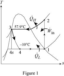
From Figure (1), write the specific enthalpy at state 3 is equal to state 4 due to throttling process.
Here, specific enthalpy at state 3 is
Express the heat removed from the cooled space.
Here, specific enthalpy at state 1, 3 and 4 is
Express heat supplied to the cooled space.
Here, specific enthalpy at state 2 is
Express the work input.
Express the COP of the cycle.
Express pressure at state 2 and state 3.
Here, pressure at state 2 and 3 is
Express quality at state 4.
Here, specific enthalpy at saturated liquid and evaporation and
Express specific entropy at state 4.
Here, specific entropy at saturated liquid and evaporation and
Conclusion:
Refer Table A-11, “saturated refrigerant-134a-temperature table”, and write the properties corresponding to initial temperature of
Here, specific entropy at state 1 is
Refer Table A-11, “saturated refrigerant-134a-tempertaure table”, and write the pressure state 2 and 3 corresponding to temperature of
Write the formula of interpolation method of two variables.
Here, the variables denote by x and y is temperature and saturated pressure respectively.
Show the saturated pressure corresponding to temperature as in Table (1).
|
Temperature |
Saturated pressure |
| 56 | 1529.1 |
| 57.9 | |
| 60 | 1682.8 |
Substitute
Substitute
Perform unit conversion of pressure at state 2 from
Refer Table A-13, “superheated refrigerant 134a”, and write the specific enthalpy at state 2 corresponding to pressure at state 2 of
Show the specific enthalpy at state 2 corresponding to specific entropy as in Table (2).
|
Specific entropy at state 2 |
Specific enthalpy at state 2 |
| 0.9164 | 280.71 |
| 0.9378 | |
| 0.9536 | 293.27 |
Use excels and substitutes the value from Table (2) in Equation (VIII) to obtain the specific enthalpy at state 2.
Refer Table A-12, “saturated refrigerant 134a-pressure table”, and write the properties corresponding to pressure at state 3 of
Here, specific enthalpy and entropy at saturated liquid is
Refer Table A-11, “saturated refrigerant-134a-tempertaure table”, and write the properties corresponding to temperature of
Substitute
Substitute
Here, specific entropy at state 4 is
Substitute
Hence, the cooling load is
Substitute
Substitute
Substitute
Hence, the COP of the cycle is
(b)
The exergy destruction in each component of the cycle and the total exergy destruction in the cycle.
(b)
Answer to Problem 32P
The exergy destruction in compressor is
Explanation of Solution
For compressor:
Express the exergy destruction in compressor.
Here, surrounding temperature is
For condenser:
Express the exergy destruction in condenser.
Here, entropy generation during process 2-3 is
For expansion valve:
For evaporator:
Express the exergy destruction in evaporator.
Here, entropy generation during process 4-1 is
Express the total exergy destruction in the cycle.
Conclusion:
Perform unit conversion of surrounding temperature from
Perform unit conversion of high temperature medium from
Perform unit conversion of low temperature medium from
Substitute
Hence, the exergy destruction in compressor is
Substitute
Hence, the exergy destruction in condenser is
Substitute
Hence, the exergy destruction in expansion valve is
Substitute
Hence, the exergy destruction in evaporator is
Substitute
Hence, the total exergy destruction in the cycle is
(c)
The second-law efficiency of the compressor, the evaporator, and the cycle.
(c)
Answer to Problem 32P
The second-law efficiency of the compressor is
Explanation of Solution
Express the exergy of the heat transferred from the low temperature medium.
Determine the second law efficiency of the cycle.
Express the total exergy destruction in the cycle.
Express the second law efficiency of the compressor.
Here, rate of work done on reversible process is
Express the exergy difference in evaporator.
Here, rate of exergy difference during process 1-4 is
Express the second law efficiency of the evaporator.
Conclusion:
Substitute
Substitute
Hence, the second-law efficiency of the cycle is
Substitute
Substitute
Hence, the second-law efficiency of the compressor is
Substitute
Substitute
Hence, the second-law efficiency of the evaporator is
Want to see more full solutions like this?
Chapter 11 Solutions
THERMODYNAMICS (LL)-W/ACCESS >CUSTOM<


- Where on the below beam is the Maxiumum Slope likely to occur? 120 Point A Point B Point C Point B or Point C B сarrow_forwardA very thin metallic sheet is placed between two wood plates of different thicknesses. Theplates are firmly pressed together and electricity is passed through the sheet. The exposed surfaces ofthe two plates lose heat to the ambient fluid by convection. Assume uniform heating at the interface.Neglect end effects and assume steady state.[a] Will the heat transfer through the two plates be the same? Explain.[b] Will the exposed surfaces be at the same temperature? Explainarrow_forwardDesign consideration requires that the surface of a small electronic package be maintained at atemperature not to exceed 82 o C. Noise constraints rule out the use of fans. The power dissipated inthe package is 35 watts and the surface area is 520 cm2 . The ambient temperature and surroundingwalls are assumed to be at 24 o C. The heat transfer coefficient is estimated to be 9.2 W/m2- oC andsurface emissivity is 0.7. Will the package dissipate the required power without violating designconstraints?arrow_forward
- Consider radiation from a small surface at 100 oC which is enclosed by a much larger surface at24 o C. Determine the percent increase in the radiation heat transfer if the temperature of the smallsurface is doubled.arrow_forwardA small electronic package with a surface area of 820 cm2 is placed in a room where the airtemperature is 28 o C. The heat transfer coefficient is 7.3 W/m2 - o C. You are asked to determine if it isjustified to neglect heat loss from the package by radiation. Assume a uniform surface temperature of78 o C and surface emissivity of 0.65 Assume further that room’s walls and ceiling are at a uniformtemperature of 16 o C.arrow_forwardA hollow metal sphere of outer radius or = 2 cm is heated internally with a variable output electricheater. The sphere loses heat from its surface by convection and radiation. The heat transfercoefficient is 22 W/ m2 - o C and surface emissivity is 0.92. The ambient fluid temperature is 20 o C andthe surroundings temperature is 14 oC. Construct a graph of the surface temperature corresponding toheating rates ranging from zero to 100 watts. Assume steady state. Use a simplified model forradiation exchange based on a small gray surface enclosed by a much larger surface at 14 o C.arrow_forward
- 2. A program to make the part depicted in Figure 26.A has been created, presented in figure 26.B, but some information still needs to be filled in. Compute the tool locations, depths, and other missing information to present a completed program. (Hint: You may have to look up geometry for the center drill and standard 0.5000 in twist drill to know the required depth to drill). Dashed line indicates - corner of original stock Intended toolpath-tangent - arc entry and exit sized to programmer's judgment 026022 (Slot and Drill Part) (Setup Instructions. (UNITS: Inches (WORKPIECE MAT'L: SAE 1020 STEEL (Workpiece: 3.25 x 2.00 x0.75 in. Plate (PRZ Location G54: ( XY 0.0 Upper Left of Fixture ( TOP OF PART 2-0 (Tool List: ) ( T04 T02 0.500 IN 4 FLUTE FLAT END MILL) #4 CENTER DRILL ' T02 0.500 TWIST DRILL N010 GOO G90 G17 G20 G49 G40 G80 G54 N020 M06 T02 (0.5 IN 4-FLUTE END MILL) R0.750 N030 S760 M03 G00 x N040 043 H02 2 Y (P1) (RAPID DOWN -TLO) P4 NO50 MOB (COOLANT ON) N060 G01 X R1.000 N070…arrow_forward6–95. The reaction of the ballast on the railway tie can be assumed uniformly distributed over its length as shown. If the wood has an allowable bending stress of σallow=1.5 ksi, determine the required minimum thickness t of the rectangular cross section of the tie to the nearest 18 in. Please include all steps. Also if you can, please explain how you found Mmax using an equation rather than using just the moment diagram. Thank you!arrow_forward6–53. If the moment acting on the cross section is M=600 N⋅m, determine the resultant force the bending stress produces on the top board. Please explain each step. Please explain how you got the numbers and where you plugged them in to solve the problem. Thank you!arrow_forward
- Solving coplanar forcesarrow_forwardComplete the following problems. Show your work/calculations, save as.pdf and upload to the assignment in Blackboard. 1. What are the x and y dimensions for the center position of holes 1,2, and 3 in the part shown in Figure 26.2 (below)? 6.0000 7118 Zero reference point 1.0005 1.0000 1.252 Bore C' bore 1.250 6.0000 .7118 0.2180 deep (3 holes) 2.6563 1.9445 3.000 diam. slot 0.3000 deep. 0.3000 wide 2.6563 1.9445arrow_forwardComplete the following problems. Show your work/calculations, save as.pdf and upload to the assignment in Blackboard. missing information to present a completed program. (Hint: You may have to look up geometry for the center drill and standard 0.5000 in twist drill to know the required depth to drill). 1. What are the x and y dimensions for the center position of holes 1,2, and 3 in the part shown in Figure 26.2 (below)? 6.0000 Zero reference point 7118 1.0005 1.0000 1.252 Bore 6.0000 .7118 Cbore 0.2180 deep (3 holes) 2.6563 1.9445 Figure 26.2 026022 (8lot and Drill Part) (Setup Instructions--- (UNITS: Inches (WORKPIECE NAT'L SAE 1020 STEEL (Workpiece: 3.25 x 2.00 x0.75 in. Plate (PRZ Location 054: ' XY 0.0 - Upper Left of Fixture TOP OF PART 2-0 (Tool List ( T02 0.500 IN 4 FLUTE FLAT END MILL #4 CENTER DRILL Dashed line indicates- corner of original stock ( T04 T02 3.000 diam. slot 0.3000 deep. 0.3000 wide Intended toolpath-tangent- arc entry and exit sized to programmer's judgment…arrow_forward
 Refrigeration and Air Conditioning Technology (Mi...Mechanical EngineeringISBN:9781305578296Author:John Tomczyk, Eugene Silberstein, Bill Whitman, Bill JohnsonPublisher:Cengage Learning