
Videos
(a)
The fraction of the refrigerant that evaporates as it is throttled to the flash chamber.
(a)
Answer to Problem 56P
The fraction of the refrigerant that evaporates as it is throttled to the flash chamber is
Explanation of Solution
Show the T-s diagram for compression refrigeration cycle as in Figure (1).
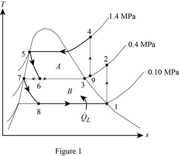
From Figure (1), write the specific enthalpy at state 5 is equal to state 6 due to throttling process.
Here, specific enthalpy at state 5 and 6 is
From Figure (1), write the specific enthalpy at state 7 is equal to state 8 due to throttling process.
Here, specific enthalpy at state 7 and 8 is
Express the fraction of the refrigerant that evaporates as it is throttled to the flash chamber
Here, specific enthalpy at saturated vapor is
Conclusion:
Perform unit conversion of pressure at state 1 from
Refer Table A-12, “saturated refrigerant-134a-pressure table”, and write the properties corresponding to pressure at state 1
Here, specific entropy and enthalpy at state 1 is
Refer Table A-13, “superheated refrigerant 134a”, and write the specific enthalpy at state 2 corresponding to pressure at state 2 of
Write the formula of interpolation method of two variables.
Here, the variables denote by x and y is specific entropy at state 2 and specific enthalpy at state 2 respectively.
Show the specific enthalpy at state 2 corresponding to specific entropy as in Table (1).
|
Specific entropy at state 2 |
Specific enthalpy at state 2 |
| 0.9306 | 256.59 |
| 0.9519 | |
| 0.9628 | 265.88 |
Substitute
Thus, the specific enthalpy at state 2 is,
Perform unit conversion of pressure at state 3 from
Refer Table A-12, “saturated refrigerant-134a-pressure table”, and write the property corresponding to pressure at state 3
Perform unit conversion of pressure at state 5 from
Refer Table A-12, “saturated refrigerant-134a-pressure table”, and write the property corresponding to pressure at state 5
Here, specific enthalpy at saturated liquid is
Substitute
Refer Table A-12, “saturated refrigerant-134a-pressure table”, and write the property corresponding to pressure at state 8
Substitute
Refer Table A-12, “saturated refrigerant-134a-pressure table”, and write the specific enthalpy at evaporation and pressure of
Substitute
Hence, the fraction of the refrigerant that evaporates as it is throttled to the flash chamber is
(b)
The rate of heat removed from the refrigerated space.
(b)
Answer to Problem 56P
The rate of heat removed from the refrigerated space is
Explanation of Solution
Express the enthalpy at state 9 by using an energy balance on the mixing chamber.
Here, the rate of total energy entering the system is
Express the mass flow rate through the flash chamber.
Here, mass flow rate through condenser is
Express The rate of heat removed from the refrigerated space.
Conclusion:
Substitute
Substitute
Substitute
Hence, the rate of heat removed from the refrigerated space is
(c)
The coefficient of performance.
(c)
Answer to Problem 56P
The coefficient of performance is
Explanation of Solution
Express compressor work input per unit mass.
Express the coefficient of performance.
Express entropy at state 4.
Here, specific entropy at state 3 is
Conclusion:
Refer Table A-12, “saturated refrigerant-134a-pressure table”, and write the property corresponding to pressure at state 3
Here, specific entropy at saturated vapor is
Substitute
Refer Table A-13, “superheated refrigerant 134a”, and write the specific enthalpy at state 4 corresponding to pressure at state 4 of
Show the specific enthalpy at state 4 corresponding to specific entropy as in Table (2).
|
Specific entropy at state 4 |
Specific enthalpy at state 4 |
| 0.9389 | 285.47 |
| 0.9436 | |
| 0.9733 | 297.10 |
Use excels and substitute value from Table (2) in Equation (IV) to get,
Substitute
Substitute
Hence, the coefficient of performance is
Want to see more full solutions like this?
Chapter 11 Solutions
THERMODYNAMICS (LL)-W/ACCESS >CUSTOM<


- Complete the following problems. Show your work/calculations, save as.pdf and upload to the assignment in Blackboard. 1. What are the x and y dimensions for the center position of holes 1,2, and 3 in the part shown in Figure 26.2 (below)? 6.0000 7118 Zero reference point 1.0005 1.0000 1.252 Bore C' bore 1.250 6.0000 .7118 0.2180 deep (3 holes) 2.6563 1.9445 3.000 diam. slot 0.3000 deep. 0.3000 wide 2.6563 1.9445arrow_forwardComplete the following problems. Show your work/calculations, save as.pdf and upload to the assignment in Blackboard. missing information to present a completed program. (Hint: You may have to look up geometry for the center drill and standard 0.5000 in twist drill to know the required depth to drill). 1. What are the x and y dimensions for the center position of holes 1,2, and 3 in the part shown in Figure 26.2 (below)? 6.0000 Zero reference point 7118 1.0005 1.0000 1.252 Bore 6.0000 .7118 Cbore 0.2180 deep (3 holes) 2.6563 1.9445 Figure 26.2 026022 (8lot and Drill Part) (Setup Instructions--- (UNITS: Inches (WORKPIECE NAT'L SAE 1020 STEEL (Workpiece: 3.25 x 2.00 x0.75 in. Plate (PRZ Location 054: ' XY 0.0 - Upper Left of Fixture TOP OF PART 2-0 (Tool List ( T02 0.500 IN 4 FLUTE FLAT END MILL #4 CENTER DRILL Dashed line indicates- corner of original stock ( T04 T02 3.000 diam. slot 0.3000 deep. 0.3000 wide Intended toolpath-tangent- arc entry and exit sized to programmer's judgment…arrow_forwardA program to make the part depicted in Figure 26.A has been created, presented in figure 26.B, but some information still needs to be filled in. Compute the tool locations, depths, and other missing information to present a completed program. (Hint: You may have to look up geometry for the center drill and standard 0.5000 in twist drill to know the required depth to drill).arrow_forward
- We consider a laminar flow induced by an impulsively started infinite flat plate. The y-axis is normal to the plate. The x- and z-axes form a plane parallel to the plate. The plate is defined by y = 0. For time t <0, the plate and the flow are at rest. For t≥0, the velocity of the plate is parallel to the 2-coordinate; its value is constant and equal to uw. At infinity, the flow is at rest. The flow induced by the motion of the plate is independent of z. (a) From the continuity equation, show that v=0 everywhere in the flow and the resulting momentum equation is მu Ət Note that this equation has the form of a diffusion equation (the same form as the heat equation). (b) We introduce the new variables T, Y and U such that T=kt, Y=k/2y, U = u where k is an arbitrary constant. In the new system of variables, the solution is U(Y,T). The solution U(Y,T) is expressed by a function of Y and T and the solution u(y, t) is expressed by a function of y and t. Show that the functions are identical.…arrow_forwardPart A: Suppose you wanted to drill a 1.5 in diameter hole through a piece of 1020 cold-rolled steel that is 2 in thick, using an HSS twist drill. What values if feed and cutting speed will you specify, along with an appropriate allowance? Part B: How much time will be required to drill the hole in the previous problem using the HSS drill?arrow_forward1.1 m 1.3 m B 60-mm diameter Brass 40-mm diameter Aluminum PROBLEM 2.52 - A rod consisting of two cylindrical portions AB and BC is restrained at both ends. Portion AB is made of brass (E₁ = 105 GPa, α = 20.9×10°/°C) and portion BC is made of aluminum (Ę₁ =72 GPa, α = 23.9×10/°C). Knowing that the rod is initially unstressed, determine (a) the normal stresses induced in portions AB and BC by a temperature rise of 42°C, (b) the corresponding deflection of point B.arrow_forward
- 30 mm D = 40 MPa -30 mm B C 80 MPa PROBLEM 2.69 A 30-mm square was scribed on the side of a large steel pressure vessel. After pressurization, the biaxial stress condition at the square is as shown. For E = 200 GPa and v=0.30, determine the change in length of (a) side AB, (b) side BC, (c) diagnonal AC.arrow_forwardPlease solve in detail this problem thank youarrow_forward0,5 mm 450 mm 350 mm Bronze A = 1500 mm² E = 105 GPa प 21.6 × 10-PC Aluminum A = 1800 mm² £ = 73 GPa = a 23.2 × 10-PC PROBLEM 2.58 Knowing that a 0.5-mm gap exists when the temperature is 24°C, determine (a) the temperature at which the normal stress in the aluminum bar will be equal to -75 MPa, (b) the corresponding exact length of the aluminum bar.arrow_forward
- 0.5 mm 450 mm -350 mm Bronze Aluminum A 1500 mm² A 1800 mm² E 105 GPa E 73 GPa K = 21.6 X 10 G < = 23.2 × 10-G PROBLEM 2.59 Determine (a) the compressive force in the bars shown after a temperature rise of 82°C, (b) the corresponding change in length of the bronze bar.arrow_forwardThe truss shown below sits on a roller at A and a pin at E. Determine the magnitudes of the forces in truss members GH, GB, BC and GC. State whether they are in tension or compression or are zero force members.arrow_forwardA weight (W) hangs from a pulley at B that is part of a support frame. Calculate the maximum possible mass of the weight if the maximum permissible moment reaction at the fixed support is 100 Nm. Note that a frictionless pin in a slot is located at C.arrow_forward
 Refrigeration and Air Conditioning Technology (Mi...Mechanical EngineeringISBN:9781305578296Author:John Tomczyk, Eugene Silberstein, Bill Whitman, Bill JohnsonPublisher:Cengage Learning