Concept explainers
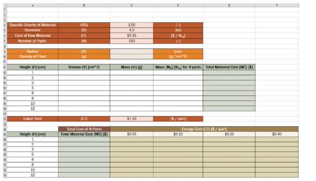
The worksheet shown was designed to calculate the cost of material that must be purchased to produce a given number of parts. The user will enter the specific gravity of the material, the diameter of the cylindrical part in units of inches, the cost of the raw material in dollars per pound-mass, and the number of parts to be manufactured. All user input is shown in red. The worksheet will calculate the radius of the cylindrical part in units of centimeters and the density of the fluid in grams per cubic centimeter. All conversions are shown in orange.
The worksheet will determine the volume and mass of a single part for a given height. Finally, the worksheet will determine the total mass of material needed to produce the desired number of parts in units of pounds-mass, and the total material cost.
The total material cost appears twice. In cells E13 to E20, a formula is written to determine the cost. In cells B26 to B33, the cells simply reference the corresponding cell in the table above. For example, B26 the formula = E13 appears.
In the bottom table, the total cost for N parts is determined by the formula:
 Total Cost = Total Material Cost + (Energy Cost + Labor Cost) × Number of Parts
- a. What should be typed into cell C9 to determine the radius in the correct units?
- b. What should be typed into cell B13 that can then be copied down column B to determine the volume of a cylindrical part in units of cubic centimeters?
- c. What should be typed into cell C13 that can then be copied through down column C to calculate the mass of each part in unit of grams?
- d. What should be typed into cell D13 that can then be copied down column D to calculate the total mass needed to produce N parts in units of pounds-mass?
- e. What should be typed into cell E13 that can then be copied down column E to calculate the total material cost?
- f. What should be typed into cell C26 that can then be copied from C26 to F33 given the energy cost in row 25 and labor cost in cell C22 to calculate the total cost of producing N parts?
Want to see the full answer?
Check out a sample textbook solution
Chapter 10 Solutions
Thinking Like an Engineer: An Active Learning Approach (4th Edition)
Additional Engineering Textbook Solutions
Vector Mechanics For Engineers
Electric Circuits. (11th Edition)
Concepts Of Programming Languages
Thermodynamics: An Engineering Approach
Modern Database Management
Management Information Systems: Managing The Digital Firm (16th Edition)
- ANSWER ASAP A Solution A is best B Solution B is best C Solution C is best D Solution D is bestarrow_forwardA distillation column with a total condenser and a partial reboiler is separating ethanol andwater at 1.0 atm. Feed is 0.32 mol fraction ethanol and it enters as a saturated liquid at 100mol/s on the optimum plate. The distillate product is a saturated liquid with 80 mol% ethanol.The condenser removes 5615 kW. The bottoms product is 0.05 mol fraction ethanol. AssumeCMO is valid.(a) Find the number of equilibrium stages for this separation. [6 + PR](b) Find how much larger the actual reflux ratio, R, used is than Rmin, i.e. R/Rmin. [3]Note: the heats of vaporization of ethanol and water are λe = 38.58 and λw = 40.645 arrow_forwardA ship of 7000 tonne displacement has a waterplane areaof 1500 m2. In passing from sea water into river water of1005 kg/m3 there is an increase in draught of 10 cm. Find the Idensity of the sea water. i would like to get the above question sloved in detail. ive attached the picture of the answer from the reeds book. just not sure of all the steps theyve used and the formula in which they started with.arrow_forward
- Plunger Gauses:) - True or False "A Plunger gage can read small fluctuations in pressure such as a change in pressure of 2 psi"arrow_forwardCushioning: (Q1) A cylinder is used to clamp onto rubber tires on an assembly line. The cylinder quickly extends and clamps onto the tire and robot puts a label onto the tire. The cylinder then retracts quickly to unclamp the tire. Which of these four cylinders is best for the job? A 0 A Selection A is best B Selection B is best (C) Selection C is best D) Selection D is best B Darrow_forwardBourdon Gauges: (Q4) - True of False "A Bourdon gauge is used to measure high pressures above 500 psi"arrow_forward
- Weight of Air: If you could collect the air in a square inch column of air starting at sea level going all the way to space, how much would it weigh? Answer with one decimal. Do not write the unit.arrow_forwardPiston Area: (Q2) A cylinder applies a force of 400 pounds in extension. If the pressure in the cylinder is 39 psi what is the area of the piston in square inches? Use πon your calculator Answer with two decimals. Do not write the unit.arrow_forwardA 2D incompressible flow has velocitycomponents u= X^2 - 2y^2 and v=aX^b y^c ,where a, b, and c are numbers. Find the values of a, b, and c Find the stream functionarrow_forward
- Please can you assist with the attached question please?arrow_forward(a) Find a second-order homogeneous linear ODE for which the given functions are solutions. (b) Show linear independence by the Wronskian. (c) Solve the initial value problem. a. cos(5x), sin(5x), y(0) = 3, y'(0) = −5 b. e-2.5x cos(0.3x), e-2.5x sin(0.3x), y(0) = 3, y'(0) = -7.5arrow_forwardSolve the IVP. a. y" 16y 17e* ; = y(0) = 6, y'(0) = -2 b. (D² + 41)y = sin(t) + ½ sin(3t) + sin(t) ; y(0) = 0, y'(0) : = 35 31arrow_forward
 Elements Of ElectromagneticsMechanical EngineeringISBN:9780190698614Author:Sadiku, Matthew N. O.Publisher:Oxford University Press
 Mechanics of Materials (10th Edition)Mechanical EngineeringISBN:9780134319650Author:Russell C. HibbelerPublisher:PEARSON
 Thermodynamics: An Engineering ApproachMechanical EngineeringISBN:9781259822674Author:Yunus A. Cengel Dr., Michael A. BolesPublisher:McGraw-Hill Education
 Control Systems EngineeringMechanical EngineeringISBN:9781118170519Author:Norman S. NisePublisher:WILEY
 Mechanics of Materials (MindTap Course List)Mechanical EngineeringISBN:9781337093347Author:Barry J. Goodno, James M. GerePublisher:Cengage Learning
 Engineering Mechanics: StaticsMechanical EngineeringISBN:9781118807330Author:James L. Meriam, L. G. Kraige, J. N. BoltonPublisher:WILEY


