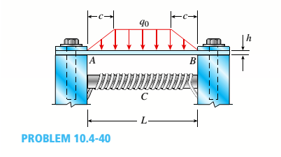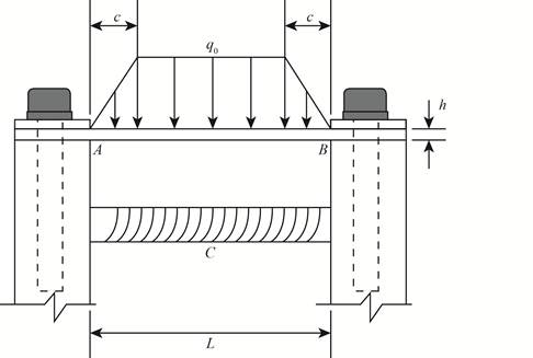
A thin steel beam AB used in conjunction with an electromagnet in a high-energy physics experiment is securely bolted to rigid supports (see figure), A magnetic field produced by coils C results in a force acting on the beam. The force is trapezoidally distributed with maximum intensity q0= 18 kN/m. The length of the beam between supports is L = 200 mm, and the dimension c of the trapezoidal load is 50 mm. The beam has a rectangular cross section with width b = 60 and height h = 20 mm.
Determine the maximum bending stress

The maximum bending stress and the maximum deflection.
Answer to Problem 10.4.40P
The maximum bending stress is
The maximum deflection in the beam is
Explanation of Solution
Given information:
Width of the rectangular cross-section is
The below figure shows the schematic diagram of the beam with parameters.

Figure-(1)
Write the expression for the equilibrium in vertical direction.
Substitute
Here, the reaction force at point A is
There is symmetry in the beam therefore the reaction forces at A and B will be same.
There is symmetry in the beam therefore the moment at A will be equal to moment at B .
Write the expression for the relation between the reaction forces at A and B .
Write the expression for the relation between the moment about A and B .
Here, the moment about A is
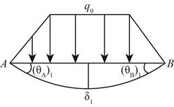
The below figure shows the deflection in the beam.

Figure-(2)
Write the expression for the compatibility.
Here, the rotation about point A is
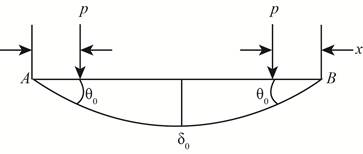
The below figure shows the deflection slope.

Figure-(3)
Write the expression for the slope from figure-(3).
Here, the load is
Write the expression for the deflection for figure-(3).
Write the expression for load.
Write the expression for load from
Write the expression for load from
Write the expression for rotation about A .
Write the expression for the deflection.
The below figure shows the moments at the ends of the beam.

Figure-(4)
Write the expression for the compatibility.
Write the expression for slope for figure-(4).
Write the expression for the deflection for figure-(4).
Write the expression for maximum deflection.
Substitute
Write the expression for the moment about C .
Write the expression for the maximum moment.
Write the expression for moment of inertia.
Here, moment of inertia is
Write the expression for the section modulus.
Write the expression for the normal stress.
Calculation:
Substitute
Substitute
Substitute
Substitute
Substitute
Substitute
Substitute
Substitute
Substitute
Conclusion:
The maximum bending stress is
The maximum deflection in the beam is
Want to see more full solutions like this?
Chapter 10 Solutions
Mechanics of Materials (MindTap Course List)
- Consider the following acid-base reaction: Fe3+(aq) +3H2O -Fe(OH)3 (s) + 3H* ← A. Using thermodynamics, calculate the equilibrium constant K at 25°C (The AG° of formation of Fe(OH)3(s) is -699 kJ/mol). B. Using the value of K you calculated in part a, if a solution contains 10-4 M Fe3+ and has a pH of 7.5, will Fe(OH)3(s) precipitate? Show all calculations necessary to justify your answer. Note that the reaction as written is for precipitation, not dissolution like Ksp-arrow_forwardA vertical force of F = 3.4 kN is applied to the hook at A as shown in. Set d = 1 m. Part A 3 m 3m 0.75 m 1.5 m. Determine the tension in cable AB for equilibrium. Express your answer to three significant figures and include the appropriate units. FAB= Value Submit Request Answer Part B Units ? Determine the tension in cable AC for equilibrium. Express your answer to three significant figures and include the appropriate units. FAC = Value Submit Request Answer Part C ? Units Determine the tension in cable AD for equilibrium. Express your answer to three significant figures and include the appropriate units.arrow_forwardConsider the heat engine operating at steady state between the two thermal reservoirs shown at the right while producing a net power output of 700 kW. If 1000 kW of heat (Q̇H) is transferred to the heat engine from a thermal reservoir at a temperature of TH = 900 K, and heat is rejected to a thermal reservoir at a temperature of TL = 300 K, is this heat engine possible? Can you answer this question for me and show all of the workarrow_forward
- 1.12 A disk of constant radius r is attached to a telescoping rod that is extending at a constant rate as shown in Fig. P1.12. Both the disk and the rod are rotating at a constant rate. Find the inertial velocity and acceleration of point P at the rim of the disk. ท2 L 0 SS P α e 0 O' êL Fig. P1.12 Rotating disk attached to telescoping rod. 60 LLarrow_forwardTwo different options A and B with brake pads for disc brakes are connected to the rope drum. The diameter of the rope drum is 150 mm. What distance must the pads B be at from the center of rotation to cover the same distance as A?A B- Width 50 mm - Width 60 mm- Evidence center 120mm - Construction power 900 N from rotation center.- Maintains a weight of 200 kgwhen the installation force is 1.4kN (μ is missing from the data)M=μF(Ry-Ri)Right answer R=187 mmarrow_forwardAssume the xy plane is level ground, and that the vertical pole shown in the diagram lies along the z-axis with its base at the origin. If the pole is 5 m tall, and a rope is used to pull on the top of the pole with a force of 400 N as shown, determine the magnitudes of the parallel and perpendicular components of the force vector with respect to the axis of the post i.e. with respect to the z-axis.arrow_forward
- 4-1 Q4: Q5: (20 Marks) Find √48 using False Position Method with three iterations. Hint: the root lies between 3 and 4. (20 Marks)arrow_forwardDetermine the angle between vectors FA and FB that is less than 180 degrees. FA is the vector drawn from the origin to point A (-4, 4, 2) while FB is the vector drawn from the origin to point B (3, 1, -3).arrow_forwardFind the resultant force vector from adding F1, F2 and F3, where … F1 = {-8i+10j-32k} N F2 is 40 N in magnitude with coordinate direction angles α, β, and γ, of 45, 120 and 60 degrees, respectively and F3 is 22 N in magnitude with transverse and azimuth angles of 65 and 40 degrees, respectively Express your final answer as a Cartesian vector as well as a magnitude with angles.arrow_forward
- A 2-kW resistance heater wire with thermal conductivity of k=20 W/mK, a diameter of D=4mm, and a length of L=0.9m is used to boil water. If the outer surface temp of the resistance wire is Ts=110 degrees C, determine the temp at the center of the wire.arrow_forwardA flat-plate solar collector is used to heat water by having water flow through tubes attached at the back of the thin solar absorber plate. The absorber plate has emmisssivity and an absorptivity of 0.9. The top surface where x=0 temp of the absorber is T0=35 degrees C, and solar radiation is incident on the basorber at 500 W/m^2 with a surrounding temp of 0 degrees C. The convection heat transfer coefficient at the absorber surface is 5 W/m^2 K, while the ambient temp is 25 degrees C. Show that the variation of the temp in the basorber plate can be expressed as T(x)=-(q0/k)x+T0, and determine net heat flux, q, absorbed by solar collector.arrow_forwardUsing properties of a saturated water, explain how you would determine the mole fraction of water vapor at the surface of a lake when the temp of the lake surface and the atmospheric pressure are specified.arrow_forward
 Mechanics of Materials (MindTap Course List)Mechanical EngineeringISBN:9781337093347Author:Barry J. Goodno, James M. GerePublisher:Cengage Learning
