
Videos
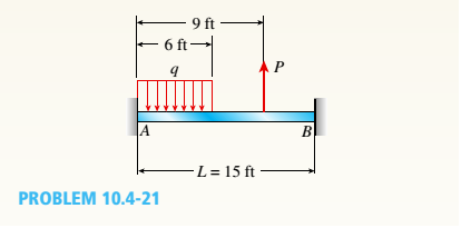
Uniform load q = 10 lb/ft acts over part of the span of fixed-end beam AB (see figure). Upward load P = 250 lb is applied 9 ft to the right of joint A. Find the reactions at A and B.
The reaction at fixed joint
Answer to Problem 10.4.21P
The reaction at
The moment at
The reaction at
The moment at
Explanation of Solution
Given information:
The length of the beam is
Figure below shows the free body diagram of fixed beam.
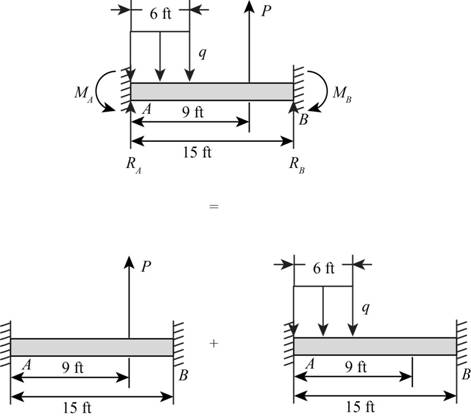
Figure-(1)
Write the expression for the reactions forces at point A.
Here, the point load is p, the length of the beam is L, the moment s acting at A and B is
Write the expression for the reactions forces at point
Write the expression for the compatibility Equation at
Here, the angles at the corresponding ends are represented by the subscript for
Write the expression for the compatibility Equation at
Write the expression for the values of slopes of type 1 loading at point
Write the expression for the value of slopes of type 1 loading at point
Write the expression for the value of slopes for type 2 loading at point
Write the expression for the values of slopes for type 2 loading at point
Write the expression for the values of slopes for type 2 loading at point
Write the expression for the values of slopes for type 2 loading at point
Substitute
Substitute
Substitute
Substitute
Substitute
Substitute
Write the expression for the fixed end moments due to the element of load
Write the expression for the fixed end moments due to the element of load
Here the uniform distributed load is
Write the expression the moment at
Substitute
Write the expression for the moment at point B.
Substitute
Write the expression for the reaction force in term of elemental load
Write the expression for the reaction force in term of elemental load
Write the expression for the reaction at point
Substitute
Write the expression for the reaction at point
Substitute
Write the expression for the reaction at point A.
Substitute
Write the expression for the reactions at point B.
Write the expression for the moment at point A.
Substitute
Write the expression for the reaction moment at point B.
Substitute
Calculation:
Substitute
Substitute
Substitute
Substitute
Conclusion:
The reaction at point
The reaction at point
The moment at point
The moment at point
Want to see more full solutions like this?
Chapter 10 Solutions
Mechanics of Materials (MindTap Course List)


- Experiment تكنولوجيا السيارات - Internal Forced convenction Heat transfer Air Flow through Rectangular Duct. objective: Study the convection heat transfer of air flow through rectangular duct. Valve Th Top Dead Centre Exhaust Valve Class CP. N; ~ RIVavg Ti K 2.11 Te To 18.8 21.3 45.8 Nath Ne Pre Calculations:. Q = m cp (Te-Ti) m: Varg Ac Acca*b Q=hexp As (Ts-Tm) 2 2.61 18.5 20.846.3 Tm = Te-Ti = 25 AS-PL = (a+b)*2*L Nu exp= Re-Vavy D heep Dh k 2ab a+b Nu Dh the- (TS-Tm) Ts. Tmy Name / Nu exp Naxe بب ارتدان العشريarrow_forwardProcedure:1- Cartesian system, 2D3D,type of support2- Free body diagram3 - Find the support reactions4- If you find a negativenumber then flip the force5- Find the internal force3D∑Fx=0∑Fy=0∑Fz=0∑Mx=0∑My=0\Sigma Mz=02D\Sigma Fx=0\Sigma Fy=0\Sigma Mz=05- Use method of sectionand cut the elementwhere you want to findarrow_forwardProcedure:1- Cartesian system, 2D3D,type of support2- Free body diagram3 - Find the support reactions4- If you find a negativenumber then flip the force5- Find the internal force3D∑Fx=0∑Fy=0∑Fz=0∑Mx=0∑My=0\Sigma Mz=02D\Sigma Fx=0\Sigma Fy=0\Sigma Mz=05- Use method of sectionand cut the elementwhere you want to findthe internal force andkeep either side of thearrow_forward
- Procedure: 1- Cartesian system, 2D3D, type of support 2- Free body diagram 3 - Find the support reactions 4- If you find a negative number then flip the force 5- Find the internal force 3D ∑Fx=0 ∑Fy=0 ∑Fz=0 ∑Mx=0 ∑My=0 ΣMz=0 2D ΣFx=0 ΣFy=0 ΣMz=0 5- Use method of section and cut the element where you want to find the internal force and keep either side of thearrow_forwardProcedure:1- Cartesian system, 2D3D,type of support2- Free body diagram3 - Find the support reactions4- If you find a negativenumber then flip the force5- Find the internal force3D∑Fx=0∑Fy=0∑Fz=0∑Mx=0∑My=0\Sigma Mz=02D\Sigma Fx=0\Sigma Fy=0\Sigma Mz=05- Use method of sectionand cut the elementwhere you want to findthe internal force andkeep either side of thearrow_forwardProcedure: 1- Cartesian system, 2(D)/(3)D, type of support 2- Free body diagram 3 - Find the support reactions 4- If you find a negative number then flip the force 5- Find the internal force 3D \sum Fx=0 \sum Fy=0 \sum Fz=0 \sum Mx=0 \sum My=0 \Sigma Mz=0 2D \Sigma Fx=0 \Sigma Fy=0 \Sigma Mz=0 5- Use method of section and cut the element where you want to find the internal force and keep either side of the sectionarrow_forward
- Procedure: 1- Cartesian system, 2(D)/(3)D, type of support 2- Free body diagram 3 - Find the support reactions 4- If you find a negative number then flip the force 5- Find the internal force 3D \sum Fx=0 \sum Fy=0 \sum Fz=0 \sum Mx=0 \sum My=0 \Sigma Mz=0 2D \Sigma Fx=0 \Sigma Fy=0 \Sigma Mz=0 5- Use method of section and cut the element where you want to find the internal force and keep either side of the sectionarrow_forwardFor each system below with transfer function G(s), plot the pole(s) on the s-plane. and indicate whether the system is: (a) "stable" (i.e., a bounded input will always result in a bounded output), (b) "marginally stable," or (c) "unstable" Sketch a rough graph of the time response to a step input. 8 a) G(s) = 5-5 8 b) G(s) = c) G(s) = = s+5 3s + 8 s² - 2s +2 3s +8 d) G(s): = s²+2s+2 3s+8 e) G(s): = s² +9 f) G(s): 8 00 == Sarrow_forwardPlease answer the following question. Include all work and plase explain. Graphs are provided below. "Consider the Mg (Magnesium) - Ni (Nickel) phase diagram shown below. This phase diagram contains two eutectic reactions and two intermediate phases (Mg2Ni and MgNi2). At a temperature of 505oC, determine what the composition of an alloy would need to be to contain a mass fraction of 0.20 Mg and 0.80 Mg2Ni."arrow_forward
- The triangular plate, having a 90∘∘ angle at AA, supports the load PP = 370 lblb as shown in (Figure 1).arrow_forwardDesign a 4-bar linkage to carry the body in Figure 1 through the two positions P1 and P2 at the angles shown in the figure. Use analytical synthesis with the free choice values z = 1.075, q= 210°, ß2 = −27° for left side and s = 1.24, y= 74°, ½ = − 40° for right side. φ 1.236 P2 147.5° 210° 2.138 P1 Figure 1 Xarrow_forwardDesign a 4-bar linkage to carry the body in Figure 1 through the two positions P1 and P2 at the angles shown in the figure. Use analytical synthesis with the free choice values z = 1.075, q= 210°, B₂ = −27° for left side and s = 1.24, y= 74°, ½ = − 40° for right side. 1.236 P2 147.5° 210° P1 Figure 1 2.138 Xarrow_forward
 Mechanics of Materials (MindTap Course List)Mechanical EngineeringISBN:9781337093347Author:Barry J. Goodno, James M. GerePublisher:Cengage Learning