Thermodynamics: An Engineering Approach
8th Edition
ISBN: 9780073398174
Author: Yunus A. Cengel Dr., Michael A. Boles
Publisher: McGraw-Hill Education
bartleby

Videos

Textbook Question
Book Icon
Chapter 9.12, Problem 130P

A turbojet is flying with a velocity of 900 ft/s at an altitude of 20,000 ft, where the ambient conditions are 7 psia and 10°F. The pressure ratio across the compressor is 13, and the temperature at the turbine inlet is 2400 R. Assuming ideal operation for all components and constant specific heats for air at room temperature, determine (a) the pressure at the turbine exit, (b) the velocity of the exhaust gases, and (c) the propulsive efficiency.

9–134E Repeat Prob. 9–133E accounting for the variation of specific heats with temperature.

a)

Expert Solution
Check Mark
To determine

The pressure at the turbine exit.

Answer to Problem 130P

The pressure at the turbine exit is 56.6psia.

Explanation of Solution

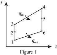
Draw the Ts diagram for pure jet engine as shown in Figure (1).

Thermodynamics: An Engineering Approach, Chapter 9.12, Problem 130P

Consider that the aircraft is stationary, and the velocity of air moving towards the aircraft is V1=900ft/s, the air will leave the diffuser with a negligible velocity (V20).

Diffuser (For process 1-2):

Write the expression for the energy balance equation for the diffuser.

E˙inE˙out=ΔE˙system (I)

Here, the rate of energy entering the system is E˙in, rate of energy leaving the system is E˙out, and the rate of change in the energy of the system is ΔE˙system.

Write the pressure and relative pressure relation for the process 1-2.

P2=P1(Pr2Pr1) (II)

Here, the specific heat ratio of air is k, pressure at state 1 is P1, pressure at state 2 is P2, relative pressure at state 1 is Pr1 and relative pressure at state 2 is Pr2.

Compressor (For process 2-3)

Write the pressure relation using the pressure ratio for the process 2-3.

P3=P4=(rp)(P2) (III)

Here, the pressure ratio is rp, pressure at state 3 is P3 and pressure at state 4 is P4.

Write the pressure and relative pressure relation for the process 2-3.

Pr3=Pr2(P3P2) (IV)

Here, pressure at state 3 is P3 and relative pressure at state 3 is Pr3.

Turbine (For process 4-5)

Write the temperature relation for the compressor and turbine.

wcomp,in=wturb,outh3h2=h4h5 (V)

Here, the specific heat at constant pressure is cp, enthalpy at state 2 is h2, enthalpy at state 3 is h3, enthalpy at state 4 is h4, enthalpy at state 5 is h5, work input to the compressor is wcomp,in and work output from turbine is wturb,out.

Write the pressure and relative pressure relation for the process 4-5.

P5=P4(Pr5Pr4) (VI)

Here, pressure at state 5 is P5, pressure at state 4 is P4, relative pressure at state 5 is Pr5 and relative pressure at state 4 is Pr4.

Conclusion:

From Table A-17E, “Ideal-gas properties of air”, obtain the following properties at the temperature of 470R.

h1=112.20Btu/lbmPr1=0.8548

The rate of change in the energy of the system (ΔE˙system) is zero for the steady state system.

Substitute 0 for ΔE˙system in Equation (I).

E˙inE˙out=0

E˙in=E˙outh1+V122=h2+V2220=h2h1+V22V122 (VII).

Here, inlet velocity is V1 or Vinlet , velocity at state 2 is V2 , enthalpy at state 2 is h2 and enthalpy at state 1 is h1.

From Table A-17E, “Ideal-gas properties of air”, obtain the following properties at the temperature of 2400R.

h4=617.22Btu/lbmPr4=367.6

Substitute 0 for V2, 112.20Btu/lbm for h1 and 900ft/s for V1, in Equation (VII).

0=h2112.20Btu/lbm+(0)(900ft/s)22h2=(112.20Btu/lbm)+(900ft/s)22(1Btu/lbm25,037ft2/s2)h2=128.37Btu/lbm

Substitute 7psia for P1, 0.8548 for Pr1, and 1.3698 for Pr2 in Equation (II).

P2=(7psia)(1.36980.8548)=11.22psia

Substitute 13 for rp, and 11.22psia for P2 in Equation (III).

P3=P4=(13)(11.22psia)=145.8psia

Substitute 145.8psia for P3, 11.22psia for P2, and 1.3698 for Pr2 in Equation (IV).

Pr3=(1.3698)(145.8psia11.22psia)=17.8

From the Table A-17, “Ideal-gas properties of air” obtain the values of enthalpy on (h3) at the relative pressure (Pr3) of 17.8 as 267.56Btu/lbm.

Substitute 617.22Btu/lbm for h4, 267.56Btu/lbm for h3, and 128.48Btu/lbm for h2.

in Equation (V).

h5=617.22Btu/lbm267.56Btu/lbm+128.48Btu/lbm=478.14Btu/lbm

From the Table A-17, “Ideal-gas properties of air” obtain the values of relative pressure (Pr4) enthalpy (h4) of 478.14Btu/lbm as 142.7.

Substitute 145.8psia for P4, 142.7 for Pr5, and 367.6 for Pr4 in Equation (VI).

P5=(145.8psia)(142.7367.6)=56.6psia

Thus, the pressure at the turbine exit is 56.6psia.

b)

Expert Solution
Check Mark
To determine

The exit velocity of the exhaust gases.

Answer to Problem 130P

The exit velocity of the exhaust gases is 3252ft/s.

Explanation of Solution

Nozzle (For process 5-6)

Write the pressure and relative pressure relation for the process 5-6.

Pr6=Pr5(P6P5) (VIII)

Here, pressure at state 6 is P6 and relative pressure at state 6 is Pr6.

Write the energy balance equation for the nozzle.

E˙inE˙out=ΔE˙system (IX)

Conclusion:

Substitute 7psia for P6, 56.6psia for P5, and 142.7 for Pr5 in Equation(VIII).

Pr6=(142.7)(7psia56.6psia)=17.65

From the Table A-17, “Ideal-gas properties of air” obtain the values of enthalpy on (h6) at the relative pressure (Pr6) of 17.66 as 266.93Btu/lbm.

The rate of change in the energy of the system (ΔE˙system) is zero for the steady state system.

Substitute 0 for ΔE˙system Equation (IX).

E˙in=E˙outh5+V522=h6+V6220=h6h5+V62V522 (X)

Here, velocity at stat 5 is V5, exit velocity is V6 or Vexit and enthalpy at state 6 is h6.

Since, V5=V2

Substitute 0 for V5, 478.14Btu/lbm for h5 and 266.93Btu/lbm for h6, in Equation (X).

0=(478.14Btu/lbm266.93Btu/lbm)V6202

V6=(2)(478.14Btu/lbm266.93Btu/lbm)(25,037ft2/s21Btu/lbm)V6=Vexit=3252ft/s

Thus, the exit velocity of the exhaust gases is 3252ft/s.

c)

Expert Solution
Check Mark
To determine

The propulsive efficiency of the turbojet engine.

Answer to Problem 130P

The propulsive efficiency of the turbojet engine is 24.2%.

Explanation of Solution

Write the expression to calculate the propulsive work done per unit mass by the turbojet engine (wp).

wp=(VexitVinlet)Vaircraft (XI).

Here, the velocity of the aircraft is Vaircraft, the velocity of the inlet air is Vinlet, and the exit velocity of the exhaust gases is Vexit.

Write the expression to calculate the heating value of the fuel per unit mass for the turbojet engine (qin).

qin=h4h3 (XII).

Here, enthalpy at state 4 is h4 and enthalpy at state 3 is h3.

Write the expression to calculate the propulsive efficiency of the turbojet engine (ηp).

ηp=wpqin (XIII).

Conclusion.

Substitute 3252ft/s for Vexit, 900ft/s for Vinlet, and 900ft/s for Vaircraft in Equation (XI).

wp=(3252ft/s900ft/s)×(900ft/s)=(2352ft/s)×(900ft/s)=2116800ft2/s2(1Btu/lbm25,037ft2/s2)=84.546Btu/lbm

Substitute 267.56Btu/lbm for h3, and 617.22Btu/lbm for h4 in Equation (XII).

qin=617.22Btu/lbm267.56Btu/lbm=349.66Btu/lbm

Substitute 349.66Btu/lbm for qin, and 84.546Btu/lbm for wp in Equation (XII).

ηp=84.546Btu/lbm349.66Btu/lbm=0.2417×100%=24.17%=24.2%

Thus, the propulsive efficiency of the turbojet engine is 24.2%.

Want to see more full solutions like this?

Subscribe now to access step-by-step solutions to millions of textbook problems written by subject matter experts!
Students have asked these similar questions
1. A 40 lb. force is applied at point E. There are pins at A, B, C, D, and F and a roller at A. a. Draw a FBD of member EFC showing all the known and unknown forces acting on it. b. Draw a FBD of member ABF showing all the known and unknown forces acting on it. c. Draw a FBD of member BCD showing all the known and unknown forces acting on it. d. Draw a FBD of the entire assembly ADE showing all the known and unknown forces acting on it. e. Determine the reactions at A and D. f. Determine the magnitude of the pin reaction at C. 40 lbs. B A 6 in. 4 in. D F -5 in.4 in 4.
A crude oil of specific gravity0.85 flows upward at a volumetric rate of flow of 70litres per second through a vertical venturimeter,with an inlet diameter of 250 mm and a throat diameter of 150mm. The coefficient of discharge of venturimeter is 0.96. The vertical differences betwecen the pressure toppings is 350mm. i) Draw a well labeled diagram to represent the above in formation  i) If the two pressure gauges are connected at the tapings such that they are positioned at the levels of their corresponding tapping points, determine the difference of readings in N/CM² of the two pressure gauges   ii) If a mercury differential manometer is connected in place of pressure gauges, to the tappings such that the connecting tube up to mercury are filled with oil determine the difference in the level of mercury column.
Can you solve it analytically using laplace transforms and with Matlab code as well please. Thank You

Chapter 9 Solutions

Thermodynamics: An Engineering Approach

Ch. 9.12 - Prob. 11PCh. 9.12 - Prob. 12PCh. 9.12 - Prob. 13PCh. 9.12 - Prob. 15PCh. 9.12 - Prob. 16PCh. 9.12 - Prob. 17PCh. 9.12 - Prob. 18PCh. 9.12 - Repeat Prob. 919 using helium as the working...Ch. 9.12 - Consider a Carnot cycle executed in a closed...Ch. 9.12 - Prob. 21PCh. 9.12 - Prob. 22PCh. 9.12 - What four processes make up the ideal Otto cycle?Ch. 9.12 - Are the processes that make up the Otto cycle...Ch. 9.12 - How do the efficiencies of the ideal Otto cycle...Ch. 9.12 - How does the thermal efficiency of an ideal Otto...Ch. 9.12 - Prob. 27PCh. 9.12 - Why are high compression ratios not used in...Ch. 9.12 - An ideal Otto cycle with a specified compression...Ch. 9.12 - Prob. 30PCh. 9.12 - Prob. 31PCh. 9.12 - Prob. 32PCh. 9.12 - An ideal Otto cycle has a compression ratio of 8....Ch. 9.12 - Prob. 35PCh. 9.12 - Prob. 36PCh. 9.12 - Prob. 37PCh. 9.12 - An ideal Otto cycle with air as the working fluid...Ch. 9.12 - Repeat Prob. 940E using argon as the working...Ch. 9.12 - Prob. 40PCh. 9.12 - Prob. 41PCh. 9.12 - Prob. 42PCh. 9.12 - Prob. 43PCh. 9.12 - Prob. 44PCh. 9.12 - Prob. 45PCh. 9.12 - Prob. 46PCh. 9.12 - Prob. 47PCh. 9.12 - Prob. 48PCh. 9.12 - Prob. 49PCh. 9.12 - Prob. 50PCh. 9.12 - Prob. 51PCh. 9.12 - Prob. 52PCh. 9.12 - Prob. 53PCh. 9.12 - Prob. 54PCh. 9.12 - Repeat Prob. 957, but replace the isentropic...Ch. 9.12 - Prob. 57PCh. 9.12 - Prob. 58PCh. 9.12 - Prob. 59PCh. 9.12 - The compression ratio of an ideal dual cycle is...Ch. 9.12 - Repeat Prob. 962 using constant specific heats at...Ch. 9.12 - Prob. 63PCh. 9.12 - An air-standard cycle, called the dual cycle, with...Ch. 9.12 - Prob. 65PCh. 9.12 - Prob. 66PCh. 9.12 - Consider the ideal Otto, Stirling, and Carnot...Ch. 9.12 - Consider the ideal Diesel, Ericsson, and Carnot...Ch. 9.12 - An ideal Ericsson engine using helium as the...Ch. 9.12 - An ideal Stirling engine using helium as the...Ch. 9.12 - Prob. 71PCh. 9.12 - Prob. 72PCh. 9.12 - Prob. 73PCh. 9.12 - Prob. 74PCh. 9.12 - Prob. 75PCh. 9.12 - For fixed maximum and minimum temperatures, what...Ch. 9.12 - What is the back work ratio? What are typical back...Ch. 9.12 - Why are the back work ratios relatively high in...Ch. 9.12 - How do the inefficiencies of the turbine and the...Ch. 9.12 - A simple ideal Brayton cycle with air as the...Ch. 9.12 - A gas-turbine power plant operates on the simple...Ch. 9.12 - Prob. 82PCh. 9.12 - Prob. 83PCh. 9.12 - Prob. 85PCh. 9.12 - 9–86 Consider a simple Brayton cycle using air as...Ch. 9.12 - 9–87 Air is used as the working fluid in a simple...Ch. 9.12 - Air is used as the working fluid in a simple ideal...Ch. 9.12 - An aircraft engine operates on a simple ideal...Ch. 9.12 - 9–91E A gas-turbine power plant operates on a...Ch. 9.12 - Prob. 92PCh. 9.12 - 9–93 A gas-turbine power plant operates on the...Ch. 9.12 - A gas-turbine power plant operates on a modified...Ch. 9.12 - Prob. 95PCh. 9.12 - Prob. 96PCh. 9.12 - Prob. 97PCh. 9.12 - Prob. 98PCh. 9.12 - 9–99 A gas turbine for an automobile is designed...Ch. 9.12 - Prob. 100PCh. 9.12 - A gas-turbine engine operates on the ideal Brayton...Ch. 9.12 - An ideal regenerator (T3 = T5) is added to a...Ch. 9.12 - Prob. 103PCh. 9.12 - Prob. 104PCh. 9.12 - Prob. 106PCh. 9.12 - A Brayton cycle with regeneration using air as the...Ch. 9.12 - Prob. 108PCh. 9.12 - Prob. 109PCh. 9.12 - Prob. 110PCh. 9.12 - Prob. 111PCh. 9.12 - Prob. 112PCh. 9.12 - Prob. 113PCh. 9.12 - Prob. 114PCh. 9.12 - Prob. 115PCh. 9.12 - A simple ideal Brayton cycle without regeneration...Ch. 9.12 - A simple ideal Brayton cycle is modified to...Ch. 9.12 - Prob. 118PCh. 9.12 - Consider a regenerative gas-turbine power plant...Ch. 9.12 - Repeat Prob. 9123 using argon as the working...Ch. 9.12 - Consider an ideal gas-turbine cycle with two...Ch. 9.12 - Repeat Prob. 9125, assuming an efficiency of 86...Ch. 9.12 - Prob. 123PCh. 9.12 - Prob. 124PCh. 9.12 - Prob. 126PCh. 9.12 - Prob. 127PCh. 9.12 - Prob. 128PCh. 9.12 - Prob. 129PCh. 9.12 - A turbojet is flying with a velocity of 900 ft/s...Ch. 9.12 - Prob. 131PCh. 9.12 - A pure jet engine propels an aircraft at 240 m/s...Ch. 9.12 - A turbojet aircraft is flying with a velocity of...Ch. 9.12 - Prob. 134PCh. 9.12 - Consider an aircraft powered by a turbojet engine...Ch. 9.12 - 9–137 Air at 7°C enters a turbojet engine at a...Ch. 9.12 - Prob. 138PCh. 9.12 - Prob. 139PCh. 9.12 - 9–140E Determine the exergy destruction associated...Ch. 9.12 - Prob. 141PCh. 9.12 - Prob. 142PCh. 9.12 - Prob. 143PCh. 9.12 - Prob. 144PCh. 9.12 - Prob. 146PCh. 9.12 - A gas-turbine power plant operates on the...Ch. 9.12 - Prob. 149PCh. 9.12 - Prob. 150RPCh. 9.12 - Prob. 151RPCh. 9.12 - Prob. 152RPCh. 9.12 - Prob. 153RPCh. 9.12 - Prob. 154RPCh. 9.12 - Prob. 155RPCh. 9.12 - Prob. 156RPCh. 9.12 - Prob. 157RPCh. 9.12 - Prob. 159RPCh. 9.12 - Prob. 161RPCh. 9.12 - Prob. 162RPCh. 9.12 - Prob. 163RPCh. 9.12 - Consider a simple ideal Brayton cycle with air as...Ch. 9.12 - Prob. 165RPCh. 9.12 - Helium is used as the working fluid in a Brayton...Ch. 9.12 - Consider an ideal gas-turbine cycle with one stage...Ch. 9.12 - Prob. 169RPCh. 9.12 - Prob. 170RPCh. 9.12 - Prob. 173RPCh. 9.12 - Prob. 174RPCh. 9.12 - Prob. 184FEPCh. 9.12 - For specified limits for the maximum and minimum...Ch. 9.12 - Prob. 186FEPCh. 9.12 - Prob. 187FEPCh. 9.12 - Helium gas in an ideal Otto cycle is compressed...Ch. 9.12 - Prob. 189FEPCh. 9.12 - Prob. 190FEPCh. 9.12 - Consider an ideal Brayton cycle executed between...Ch. 9.12 - An ideal Brayton cycle has a net work output of...Ch. 9.12 - In an ideal Brayton cycle, air is compressed from...Ch. 9.12 - In an ideal Brayton cycle with regeneration, argon...Ch. 9.12 - In an ideal Brayton cycle with regeneration, air...Ch. 9.12 - Consider a gas turbine that has a pressure ratio...Ch. 9.12 - An ideal gas turbine cycle with many stages of...Ch. 9.12 - Prob. 198FEP
Knowledge Booster
Background pattern image
Mechanical Engineering
Learn more about
Need a deep-dive on the concept behind this application? Look no further. Learn more about this topic, mechanical-engineering and related others by exploring similar questions and additional content below.
Similar questions
SEE MORE QUESTIONS
Recommended textbooks for you
Text book image
Elements Of Electromagnetics
Mechanical Engineering
ISBN:9780190698614
Author:Sadiku, Matthew N. O.
Publisher:Oxford University Press
Text book image
Mechanics of Materials (10th Edition)
Mechanical Engineering
ISBN:9780134319650
Author:Russell C. Hibbeler
Publisher:PEARSON
Text book image
Thermodynamics: An Engineering Approach
Mechanical Engineering
ISBN:9781259822674
Author:Yunus A. Cengel Dr., Michael A. Boles
Publisher:McGraw-Hill Education
Text book image
Control Systems Engineering
Mechanical Engineering
ISBN:9781118170519
Author:Norman S. Nise
Publisher:WILEY
Text book image
Mechanics of Materials (MindTap Course List)
Mechanical Engineering
ISBN:9781337093347
Author:Barry J. Goodno, James M. Gere
Publisher:Cengage Learning
Text book image
Engineering Mechanics: Statics
Mechanical Engineering
ISBN:9781118807330
Author:James L. Meriam, L. G. Kraige, J. N. Bolton
Publisher:WILEY
Power Plant Explained | Working Principles; Author: RealPars;https://www.youtube.com/watch?v=HGVDu1z5YQ8;License: Standard YouTube License, CC-BY