
Concept explainers
Videos
(a) Assuming the passive sign convention, obtain an expression for the voltage across the 1 Ω resistor in the circuit of Fig. 9.41 which is valid for all t > 0. (b) Determine the settling time of the resistor voltage.
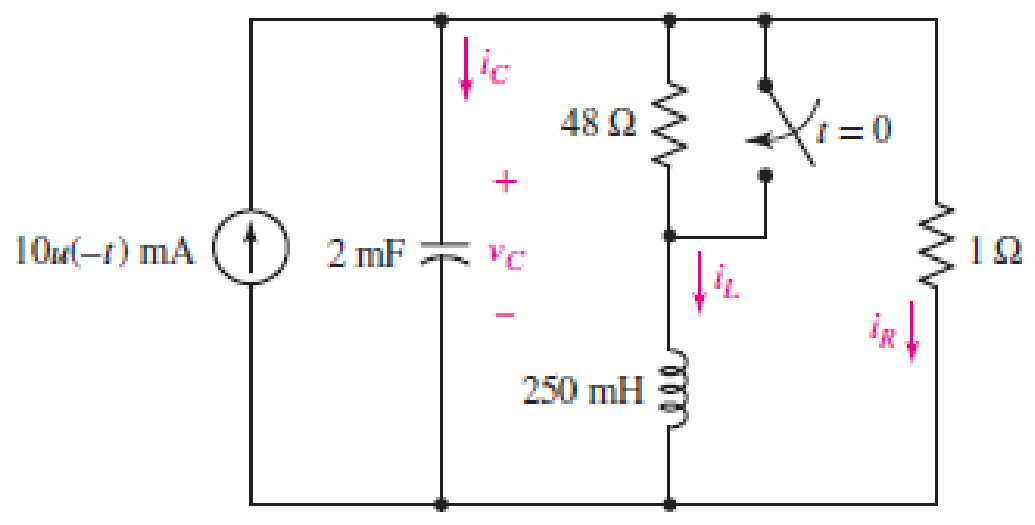
■ FIGURE 9.41
(a)
Obtain an expression for voltage across
Answer to Problem 15E
The expression for voltage across
Explanation of Solution
Formula used:
The expression for the exponential damping coefficient or the neper frequency is as follows:
Here,
The expression for the resonating frequency is as follows:
Here,
The expression for the two solutions of the characteristic equation of a parallel
Here,
The expression for the natural response of the parallel
Here,
Calculation:
The redrawn circuit diagram is given in Figure 1 for
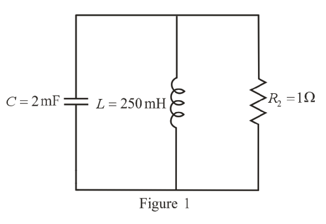
Refer to the redrawn Figure 1:
Substitute
Substitute
As value of neper frequency
Substitute
Substitute
The unit-step forcing function as a function of time which is zero for all values of its argument less than zero and which is unity for all positive values of its argument.
Here,
So, at
The capacitor and the inductor are connected in the circuit for long time.
So, the capacitor behaves as open circuit and the inductor behaves as short circuit.
The redrawn circuit diagram is given in Figure 2 for
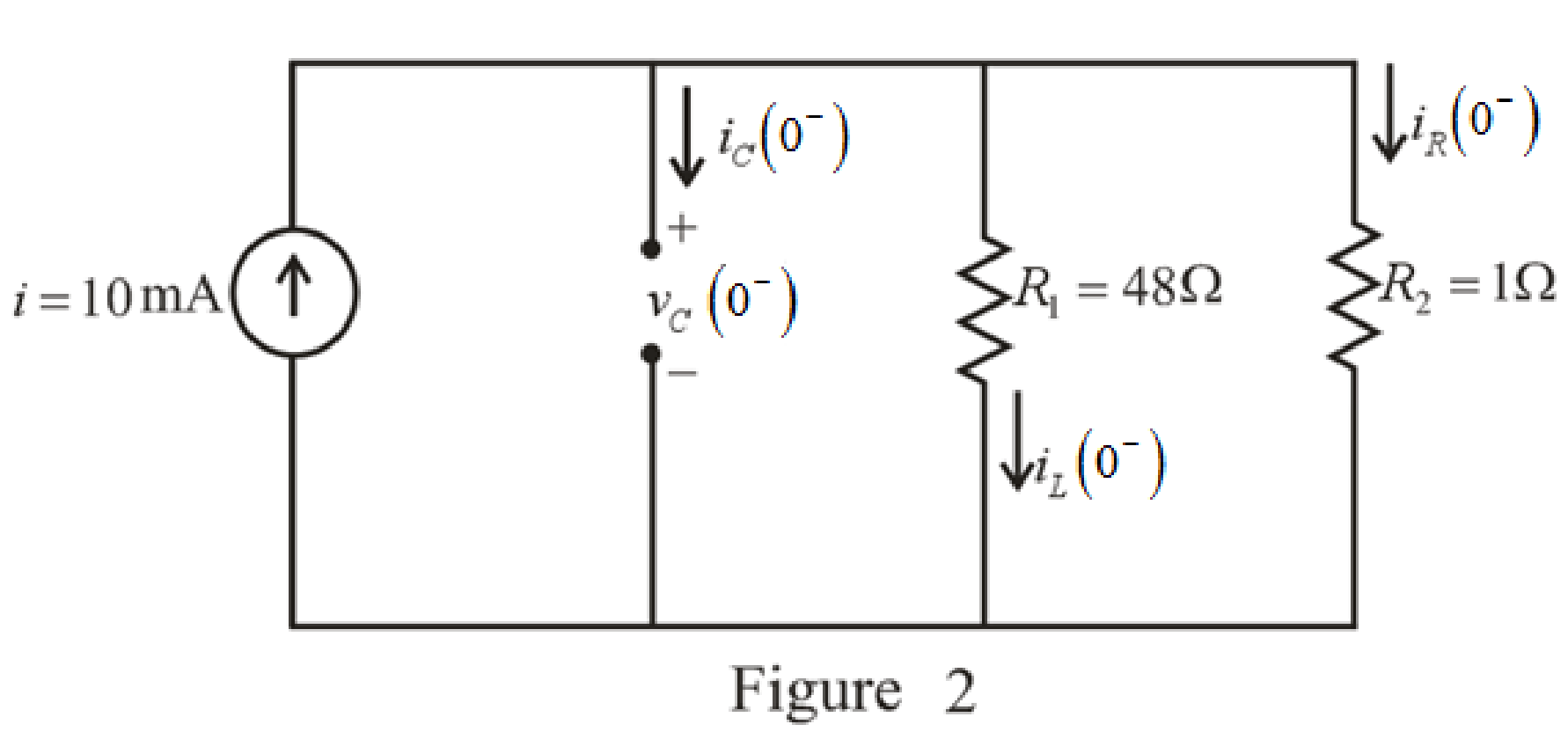
Refer to the redrawn Figure 2:
The expression for the current flowing in the
Here,
Substitute
The expression for the voltage across the
Here,
Substitute
The switch closes at
The capacitor does not allow sudden change in the voltage and the capacitor does not allow sudden change in the current.
So,
As parallel branches have same voltage across them, so, voltage across resistor
Therefore,
The redrawn circuit diagram is given in Figure 3 for
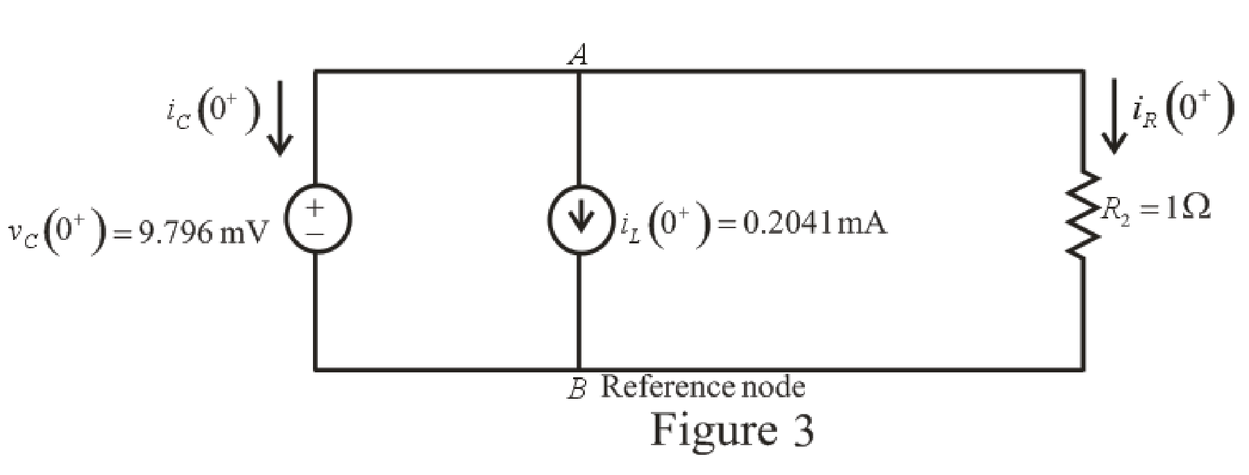
Refer to the redrawn Figure 3:
The expression for the current flowing in the resistor
Here,
Substitute
Apply KCL at node
Here,
Substitute
Rearrange for
Substitute
Substitute
The voltage across the resistor
Substitute
Rearrange for
The expression for the current flowing through the
Substitute
Rearrange for
Substitute
The current flowing through the
Substitute
Rearrange for
Substitute
Rearrange for
Substitute
Substitute
Conclusion:
Thus, expression for voltage across
(b)
Find settling time of the resistor voltage.
Answer to Problem 15E
The settling time is
Explanation of Solution
Calculation:
Function for voltage across resistor
The maximum value of voltage
Substitute
So, the maximum value of voltage
Settling time is the time at which the value of the voltage
The expression for the voltage
Here,
Substitute
Substitute
Since the component
So, the new equation is:
Rearrange equation (20).
Take natural logarithm both sides.
Conclusion:
Thus, the settling time is
Want to see more full solutions like this?
Chapter 9 Solutions
ENGINEERING CIRCUIT...(LL)>CUSTOM PKG.<


- Solve this experiment with an accurate solution, please. Thank you.arrow_forwardA lossless uncharged transmission line of characteristic impedance Zo = 600 and length T = 1us is connected to a 180 load. If this transmission line is connected at t = 0 to a 90 V dc source with an internal resistance of 900, from a bounce diagram of this system sketch (a) the voltage at z=0, z=L, and z = L/2 for up to 7.25μs and (b) calculate the load voltage after an infinite amount of time.arrow_forwardA lossless uncharged transmission line of length L = 0.45 cm has a characteristic impedance of 60 ohms. It is driven by an ideal voltage generator producing a pulse of amplitude 10V and width 2 nS. If the transmission line is connected to a load of 200 ohms, sketch the voltage at the load as a function of time for the interval 0 < t < 20 nS. You may assume that the propagation velocity of the transmission is c/2.arrow_forward
- The VSWR (Voltage Standing Wave Ratio) is measured to be 2 on a transmission line. Find two values of the reflection coefficient with one corresponding to Z > Zo and the other to Zarrow_forwardA dc voltage of unknown value Vand internal resistance Reis connected through a switch to a lossless transmission line of Zo = 1000. If the first 5 μS of the voltages at z = 0 and z = L are observed to be as shown below, calculate Vo, RG, the load resistanceR,, and the transit time T. 100 + [V]:-0. V 90 [V]:-V 100 75 I, Տ 1,μs 2 4 6 0 2 4 6arrow_forwardA lossless open circuited transmission line behaves as an equivalent capacitance of Ceq = Tan (BL) Show for BL << 1 that Ceq = C'L where L is the length of the transmission line and wZo C' is the lumped parameter capacitance per unit length of the transmission line. Hint: For x small, Tan(x) = x.arrow_forward= A generator with VG 300V and R = 50 is connected to a load R = 750 through a 50 lossless transmission line of length L = 0.15 m. (a) Compute Zin, the input impedance of the line at the generator end. (b) Compute and V. (c) Compute the time-average power Pin delivered to the line. (d) Compute VL, IL, and the time-average power delivered to the load, PL (e) How does Pin compare to PL? Explain.arrow_forwardFor the regulated power supply circuit, assume regular diodes with 0.7V forward drop. Use a 15V (peak), 60Hz sine wave at the transformer secondary and assume a maximum ripple level of 1V. (a) Compute the unknown components needed to design 10V DC supply.Hint: find R first, and then C. What is the ripple level for C=22µF?Sketch the rectified, filtered, and regulated outputsarrow_forwardA) Find the solution of B) Find the convolution of Sewt (t-π)dt 8 e-atu(t)e-blu(t)arrow_forwardConsider the signal: f(t)= 0, ㅠ 1 Use the Fourier transform formula to find F(w). otherwisearrow_forwardA half-wave controlled rectifier is supplied by a 230 Vrms voltage source and has load resistance of 2502. Calculate the delay angle a that produces a load-absorbed power of 200W.arrow_forwardQ6 The FET shown in Fig. 1.43 has gm = 3.4 mS and rd =100 K. Find the approximate lower cutoff frequency. Ans: 735.1 Hz. 25V 1.5ΜΩ 20 ΚΩ 0.02µF HH 2ΚΩ 0.02µF HH 330kQ 820 ΩΣ 1.0µF www 40ΚΩarrow_forwardarrow_back_iosSEE MORE QUESTIONSarrow_forward_ios
 Introductory Circuit Analysis (13th Edition)Electrical EngineeringISBN:9780133923605Author:Robert L. BoylestadPublisher:PEARSON
 Delmar's Standard Textbook Of ElectricityElectrical EngineeringISBN:9781337900348Author:Stephen L. HermanPublisher:Cengage Learning
 Programmable Logic ControllersElectrical EngineeringISBN:9780073373843Author:Frank D. PetruzellaPublisher:McGraw-Hill Education
 Fundamentals of Electric CircuitsElectrical EngineeringISBN:9780078028229Author:Charles K Alexander, Matthew SadikuPublisher:McGraw-Hill Education
 Electric Circuits. (11th Edition)Electrical EngineeringISBN:9780134746968Author:James W. Nilsson, Susan RiedelPublisher:PEARSON
 Engineering ElectromagneticsElectrical EngineeringISBN:9780078028151Author:Hayt, William H. (william Hart), Jr, BUCK, John A.Publisher:Mcgraw-hill Education,