
Concept explainers
Videos
With regard to the circuit presented in Fig. 9.42, (a) obtain an expression for v(t) which is valid for all t > 0; (b) calculate the maximum inductor current and identify the time at which it occurs; (c) determine the settling time.
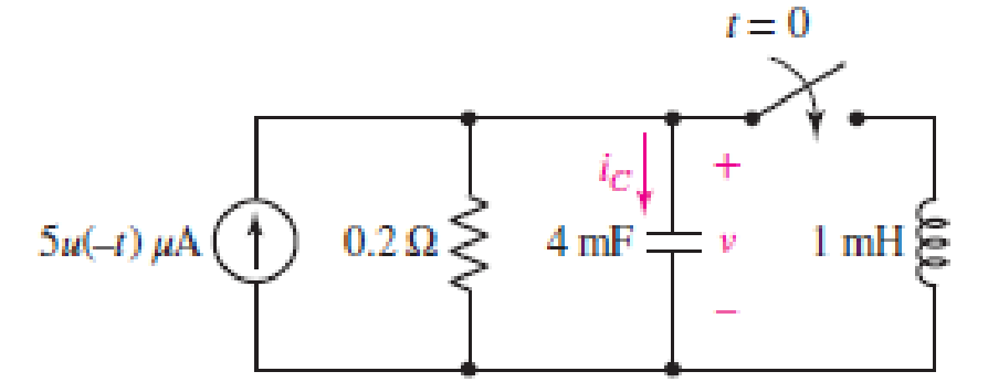
FIGURE 9.42
(a)
Find the equation for voltage
Answer to Problem 16E
The equation of voltage is
Explanation of Solution
Formula used:
The expression for the exponential damping coefficient is as follows:
Here,
The expression for the resonating frequency is as follows:
Here,
The expression for the two solutions of the characteristic equation of a parallel
Here,
Here,
Calculation:
The redrawn circuit is shown in Figure 1 as follows:
Refer to the Figure 1,
At
The current across inductor is zero because inductor is not energized.
The expression for voltage
Here,
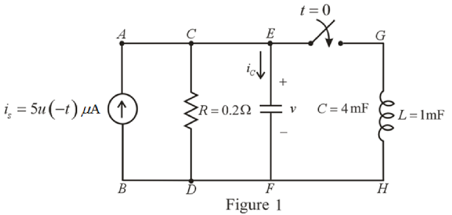
The redrawn circuit at
Refer to the Figure 2:
The expression for the voltage across capacitor at
Substitute
The expression for the natural response of voltage for capacitor in the parallel
Substitute
Rearrange for
At
Therefore,
So,
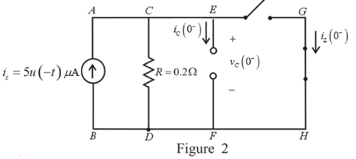
The redrawn circuit is shown in Figure 3 as follows:
Refer to the Figure 3:
The current across resistor
The expression for KCL at node
Here,
Substitute
The expression for current flowing through capacitor for
Here,
At
The circuit diagram is redrawn as shown in Figure 4 for
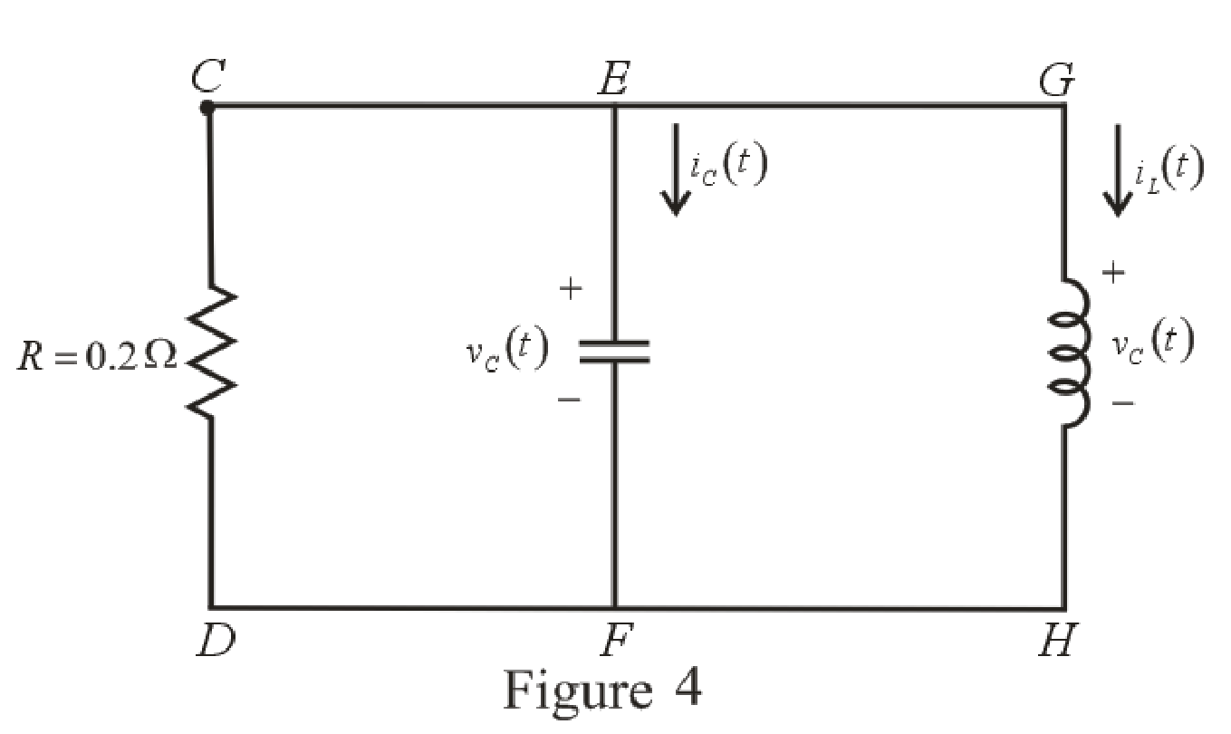
Refer to the redrawn Figure 4:
Substitute
Substitute
As value of exponential frequency
Substitute
Substitute
Differentiate equation (6) both the sides with respect to time
Substitute
Substitute
Substitute
Rearrange for
Rearrange for
Substitute
Substitute
Therefore, voltage across inductor
Conclusion:
Thus, the voltage
(b)
Find the maximum inductor current and the time of occurrence.
Answer to Problem 16E
The maximum inductor current
Explanation of Solution
Calculation:
Refer to the Figure 4:
The expression for inductor current is:
Substitute
For the maximum positive value of inductor current, take the derivative of its equation and then, equate it to zero to find the time at which maximum value of current occurs.
Differentiate equation (14) both the sides with respect to time
Equate the equation to zero.
Rearrange the equation.
Take log both the sides.
Rearrange for
Substitute
This is the maximum inductor current.
Conclusion:
Thus, the maximum inductor current is
(c)
Find the settling time.
Answer to Problem 16E
The settling time of the voltage
Explanation of Solution
Calculation:
The settling time is the time at which inductor current reaches to
Substitute
The settling time is the time at which the inductor current is decreased to
Equation (17) is solved by scientific calculator which can determine the value of time
Conclusion:
Thus, the settling time of the inductor current
Want to see more full solutions like this?
Chapter 9 Solutions
ENGINEERING CIRCUIT...(LL)>CUSTOM PKG.<


- Note: You might want to do the last question first because the last question asks you to write some python code to calculate the zeros and poles. You could use that code here to help you (except the first problem which you should be able to do by inspection alone) Find the poles and zeros for each of the following transfer functions 1. S+3 H(s) = 8 5 2. H(s): = s238 +1 s2 +48 +3 3. s(s+4) H(s) s3+2s23s 4. 82-586 H(s) = - 8382-68 5. H(s): = s2 +48 +3 s45836s2 - 6arrow_forwardWrite python program to plot the zeros and poles if a user provides the coefficients for the numerator and denominator of the transfer function. Since the zeros and poles can be complex, this plot is essentially and argand diagram, where the x axis is the real component and the y axis the imaginary component of a given zero or pole. Create a method called plot-poles zeros(num, den) which takes two lists containing the coefficients. Here is an example and the resulting plot. num [1, 3, 7] # yields zeros at -1.5 +/- 2.17945j den = [1, 4, 5, 3] # yields poles at -2.46557, -0.7672143 +/- 0.7925519j plot_poles_zeros(num, den) Imaginary Page 2 Pole-Zero Plot 3 Zeros × Poles 2 1 -2 1 * Real When you write your code you are only allowed to use the packages numpy and matplotlib. Make sure you label the axes, provide a legend and give a title to your plot (See the example plot). Hint: numpy has a method called roots. When given a list of numbers corresponding to the coefficients of a polynomial,…arrow_forwarda) [10] Compute the zeros and poles for the following transfer function: $2 +5s+6 H(s): s2 +3s+2 b) [10] Factor both polynomials in the numerator and denominator. What does this tell you about one of the poles and zeros you found in a)?arrow_forward
- Pls show neat and whole solutionarrow_forward2. Find the steady-state current i(t) in the circuit shown below when Vs(t) = 100cos(500t -30) volts. Express your answer in cosine form i.e., i(t) Im cos (oot+). (20 pts) LLE) 10052 Vs (E) 40uF 0.3 Harrow_forward1. Determine the thevenin equivalent circuit (i.e., Vth, Zth) from the terminals a-b in the circuit shown below. (15 pts) j512 1052 1020arrow_forward
- Need schematic diagram for this computerized don't use guidelines answer okk will dislikearrow_forwardthe question with its answer but i still dont see how the expansion and the calculation done. please show detailed steps.arrow_forwardQ6) Find the current density J for the magnetic field intensity vectors: (a) H = x²yax + y²zay - 2xzaz pzap + p³a + 3pz²a (b) H = sin cos (c) H = a,arrow_forward
 Introductory Circuit Analysis (13th Edition)Electrical EngineeringISBN:9780133923605Author:Robert L. BoylestadPublisher:PEARSON
 Delmar's Standard Textbook Of ElectricityElectrical EngineeringISBN:9781337900348Author:Stephen L. HermanPublisher:Cengage Learning
 Programmable Logic ControllersElectrical EngineeringISBN:9780073373843Author:Frank D. PetruzellaPublisher:McGraw-Hill Education
 Fundamentals of Electric CircuitsElectrical EngineeringISBN:9780078028229Author:Charles K Alexander, Matthew SadikuPublisher:McGraw-Hill Education
 Electric Circuits. (11th Edition)Electrical EngineeringISBN:9780134746968Author:James W. Nilsson, Susan RiedelPublisher:PEARSON
 Engineering ElectromagneticsElectrical EngineeringISBN:9780078028151Author:Hayt, William H. (william Hart), Jr, BUCK, John A.Publisher:Mcgraw-hill Education,