
Concept explainers
Videos
For the circuit represented by Fig. 9.44, the two resistor values are R1 = 0.752 Ω and R2 = 1.268 Ω, respectively. (a) Obtain an expression for the energy stored in the capacitor, valid for all t > 0; (b) determine the settling time of the current labeled iA.
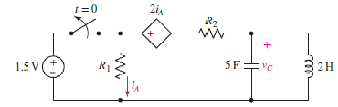
FIGURE 9.44
(a)
Find the expression for the energy stored in the capacitor, valid for all
Answer to Problem 20E
The expression for the energy stored in the capacitor, valid for all
Explanation of Solution
Given Data:
The value of the resistor
Formula used:
The expression for the exponential damping coefficient or the neper frequency is as follows:
Here,
The expression for the resonating frequency is as follows:
Here,
The expression for the two solutions of the characteristic equation of a parallel
Here,
The expression for the natural response of the parallel
Here,
The expression for the energy stored in the capacitor is as follows:
Here,
Calculation:
The capacitor and the inductor are connected in the circuit for long time.
So, the capacitor behaves as open circuit and the inductor behaves as short circuit.
The redrawn circuit diagram is given in Figure 1 for
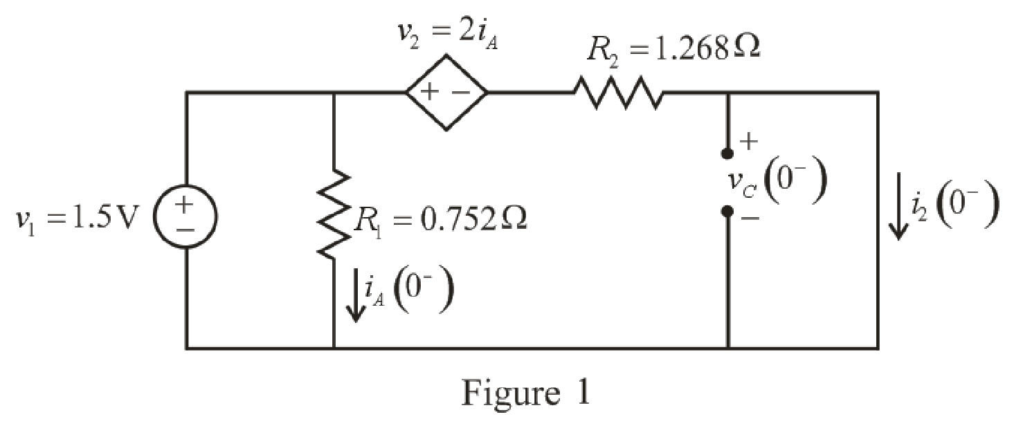
Refer to the redrawn Figure 1:
As parallel branches have same voltage so voltage across
The expression for the current flowing through
Here,
Substitute
The expression for the current flowing through the
Here,
Substitute
Substitute
As parallel branches have same voltage and the voltage across the short circuit branch has
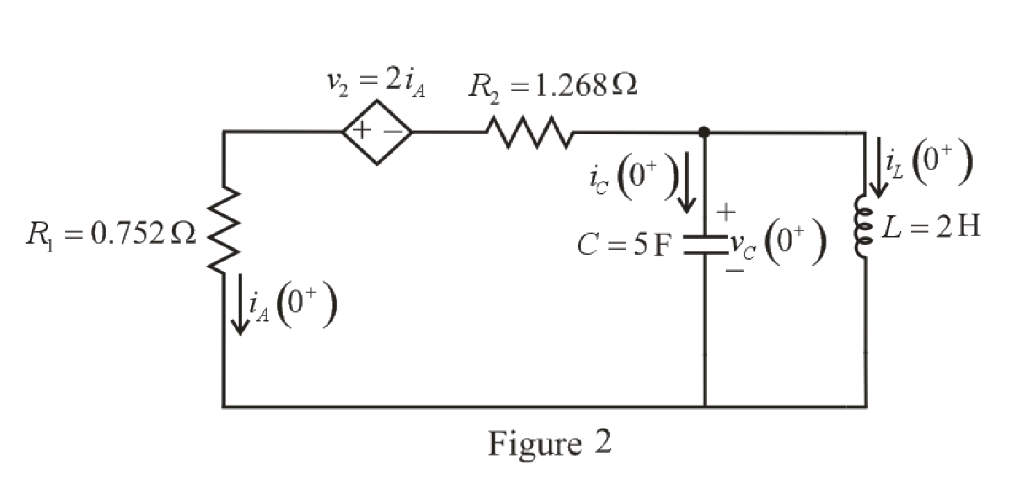
The capacitor does not allow sudden change in the voltage and the inductor does not allow sudden change in current.
So,
Therefore, the voltage across the
The redrawn circuit diagram is given in Figure 2 at
 l
l
Refer to the redrawn Figure 2:
As the voltage across the he
To find equivalent resistance across the capacitor, a
The redrawn circuit diagram is given in Figure 3.
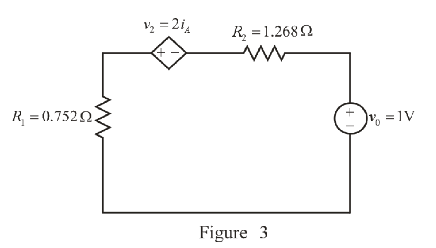
Refer to the redrawn Figure 3:
Apply KVL in the circuit.
Here,
Substitute
Rearrange for
The expression for the equivalent resistance the circuit is as follows:
Here,
Substitute
Substitute
Substitute
Here, the exponential damping coefficient is greater than the resonating frequency,
So, the response of the parallel
Substitute
Substitute
Substitute
Substitute
The voltage across the capacitor at
Substitute
Rearrange for
The expression for the current flowing through the
Substitute
Rearrange for
Substitute
The current flowing through the
Substitute
Rearrange for
Substitute
Rearrange for
Substitute
Substitute
Substitute
So, the energy stored in the capacitor, valid for all
Conclusion:
Thus, the expression for the energy stored in the capacitor, valid for all
(b)
Find the settling time of the current
Answer to Problem 20E
The settling time of current
Explanation of Solution
Calculation:
The redrawn circuit diagram is given in Figure 4.
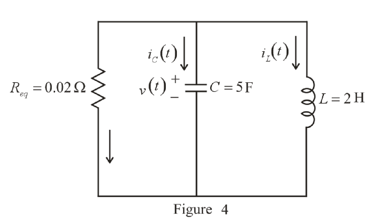
Refer to the redrawn Figure 4:
The expression for the current flowing in the left hand mesh at
Here,
Substitute
Differentiate both side of the equation (19).
The maximum value is obtained when derivative is equated to zero.
Rearrange equation (20).
Take natural logarithm both sides.
Rearrange for
Substitute
So, the value of the maximum current flowing in the left hand mesh is
Settling time is the time at which the value of the current reaches
The expression for the current at
Here,
Substitute
The value of current flowing in the left hand mesh at
Substitute
Since the component
So, the new equation is:
Rearrange equation (22).
Take natural logarithm both sides.
Rearrange for
So, the settling time of the currentflowing in the left hand mesh
Conclusion:
Thus, the settling time of current
Want to see more full solutions like this?
Chapter 9 Solutions
ENGINEERING CIRCUIT...(LL)>CUSTOM PKG.<


- Fundamentals of Energy Systems HW 4 Q4arrow_forwardFundamentals of Energy Systems HW 4 Q6arrow_forwardConstruct a battery pack to deliver 360V and 450-mile range for a vehicle that consumes 200 Wh/mile, from prismatic cells with 25Ah and 3.6 V. Physical dimensions of the cell are 0.5 cm thickness, 20 cm width and 40 cm length. a) Report configuration of the battery pack. 10-points b) Resistance of each cell is 0.05 Ohm, calculate the total internal resistance of the battery pack. 10-points c) Calculate the voltage drop during discharge when the battery is discharged at 100A. 10-points d) Calculate the amount of anode and cathode to build a prismatic cell with 25Ah capacity. Assume the cell chemistry as: Si anode and [Li(Ni1/3Co1/3Mn1/3)O2] cathode. Atomic weight of elements: Li=7, Si = 28, Ni=58, Co=59, Mn=55, O=16, 10-points e) Calculate the theoretical specific energy (Wh/kg) and practical energy density (Wh/liter) of the battery pack. 10-points f) Calculate the thickness on anode and cathode coating assuming each electrode has 30%…arrow_forward
- I need help with this problem and an explanation of the solution for the image described below. (Introduction to Signals and Systems)arrow_forwardDesign a battery pack for an electric bike that consumes in average 10Wh/mile and drive 30 miles per charge. The battery state of charge window is 80%. Design the battery by using new commercial cylindrical cells with 20mm diameter and 80mm height. The battery is constructed based on graphite anode C6 and cathode Li(Ni0.8Co0.15Al0,05)O2 that provides 3.75V at the cell level and 10Ah capacity. Density of anode is 2.2 g/cm3 and density of cathode is 4.5 g/cm3. Report on the battery pack configuration if the required battery pack voltage is 75 volts. If the thickness of anode and cathode is limited to 130 microns (130 x 10-4 cm) calculate the total electrode surface area in each cell. Assume the porosity of electrodes are 30%. Calculate the weight of active materials (anode and cathode) in grams and the total current collector’s and electrolyte membrane areas in (cm2).arrow_forwardDO NOT USE AI NEED HANDWRITTEN SOLUTION Find total impedance of circuit in polar form and power factor.arrow_forward
- Do NOT WANT AI. need diagram fully labeled pleasearrow_forwardCalculate the current magnitude in the coils e1, e2 of theMagnetic circuit, if:ɸa = 3.00 x 10^-3 Wb, φb = 0.80 x 10^-3 Wb, ɸc = 2.20 x 10^-3 Wb L ab = 0.10 m,A ab = 5.0 cm^2L afeb = L acdb = 0.40 mA afeb = A acdb = 20 cm^2 MATERIAL CHARACTERISTICSH (At/m) 240 350 530 1300 5000 9000B (T) 0.7 0.9 1.1 1.3 1.5 1.6arrow_forwardA toroid magnetic circuit is composed of three sections A, B and C, thesection C has an air gap, section A has an 850 round coil thatconsumes a current of 1.2 A. the physical and magnetic properties of each sectionare: Section A: Length = 80 mm, Cross section = 120 mm^2, μr = 400 Section B: Length = 60 mm, Cross section = 40 mm^2, μr = 250 Section C: Length = 50 mm, Cross section = 200 mm^2, μr = 600 Gap: Length = 1 mm, Cross section = 40 mm^2, μr = 1 Calculate:The magnetic field density in each of the sectionsarrow_forward
 Introductory Circuit Analysis (13th Edition)Electrical EngineeringISBN:9780133923605Author:Robert L. BoylestadPublisher:PEARSON
 Delmar's Standard Textbook Of ElectricityElectrical EngineeringISBN:9781337900348Author:Stephen L. HermanPublisher:Cengage Learning
 Programmable Logic ControllersElectrical EngineeringISBN:9780073373843Author:Frank D. PetruzellaPublisher:McGraw-Hill Education
 Fundamentals of Electric CircuitsElectrical EngineeringISBN:9780078028229Author:Charles K Alexander, Matthew SadikuPublisher:McGraw-Hill Education
 Electric Circuits. (11th Edition)Electrical EngineeringISBN:9780134746968Author:James W. Nilsson, Susan RiedelPublisher:PEARSON
 Engineering ElectromagneticsElectrical EngineeringISBN:9780078028151Author:Hayt, William H. (william Hart), Jr, BUCK, John A.Publisher:Mcgraw-hill Education,