
Consider the circuit depicted in Fig. 9.40. (a) Obtain an expression for iL(t) valid for all t > 0. (b) Obtain an expression for iR(t) valid for all t > 0. (c) Determine the settling time for both iL and iR.
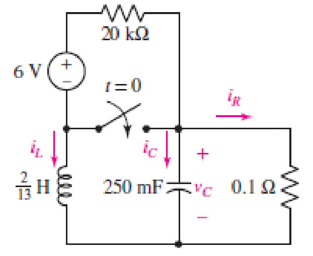
■ FIGURE 9.40
(a)
Obtain an expression for
Answer to Problem 13E
The current across inductor
Explanation of Solution
Formula used:
The expression for the exponential damping coefficient in parallel
Here,
The expression for the resonating frequency in parallel
Here,
The expression for the two solutions of the characteristic equation of a parallel
Here,
The expression for the natural response of the parallel
Here,
Calculation:
The redrawn circuit is shown in Figure 1 as follows:
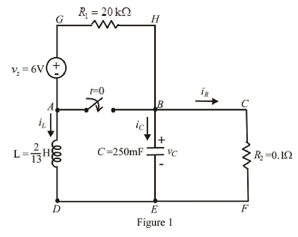
Refer to the Figure 1:
At
Here,
The redrawn circuit at
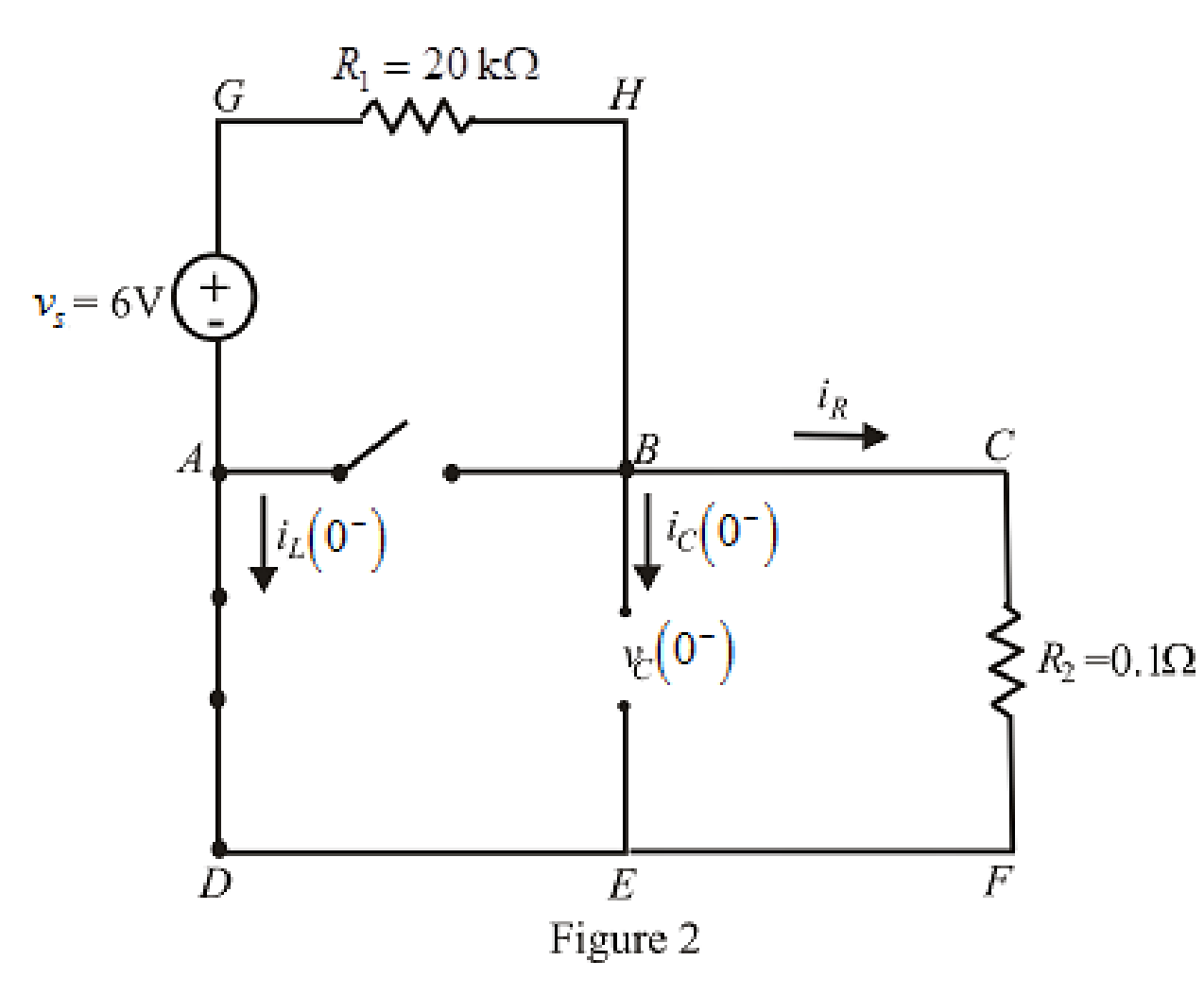
Refer to the Figure 2:
Substitute
The expression for voltage
Here,
Substitute
Substitute
Rearrange for
At
The voltage across inductor is same as voltage across capacitor due to parallel circuit and thus, the expression for voltage across inductor is:
The redrawn circuit is shown in Figure 3 as follows:
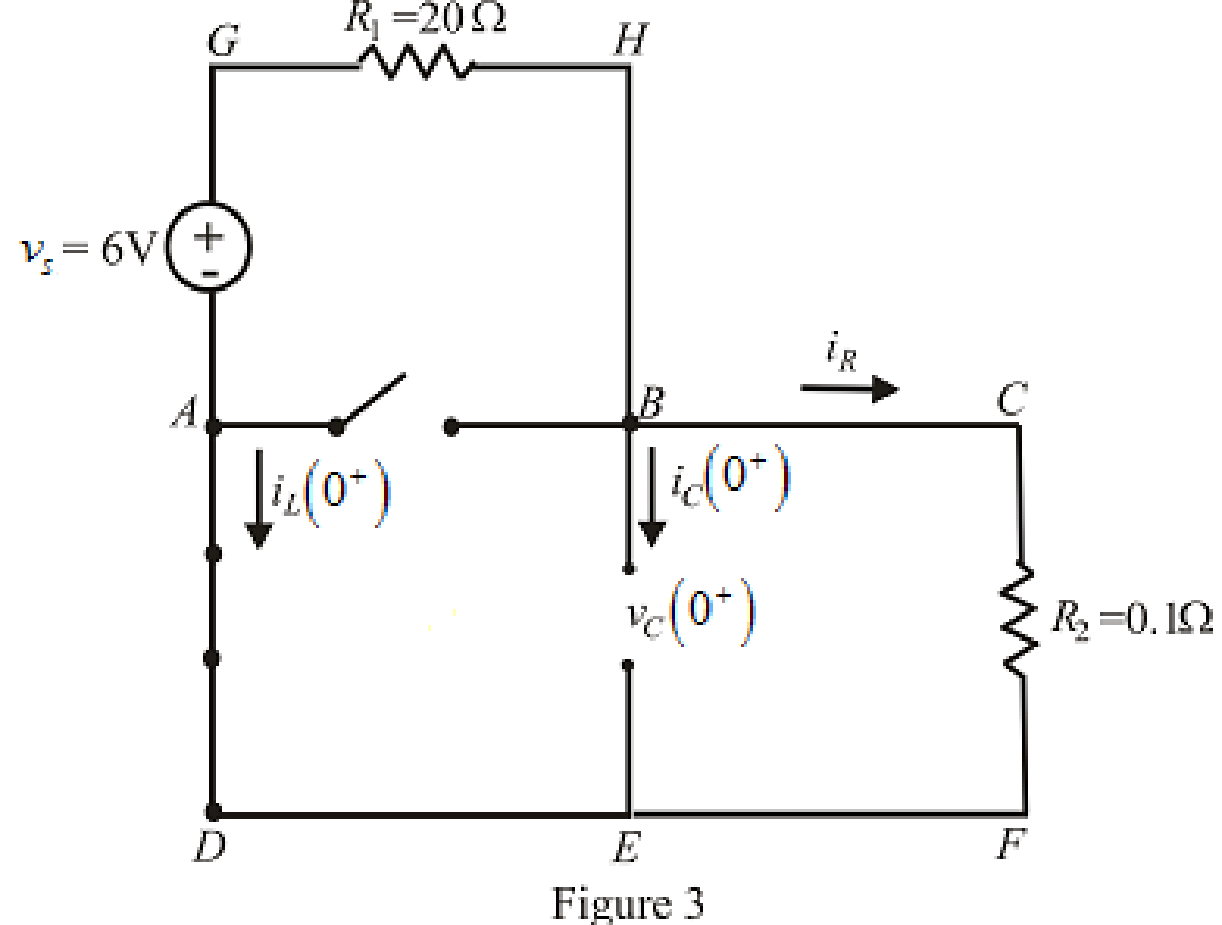
Refer to the Figure 3:
Substitute
Substitute
Differentiate equation (5) both the sides with respect to time
The expression for the voltage across inductor at time
At
Substitute
Rearrange for
Substitute
At
The circuit diagram is redrawn as shown in Figure 4 for
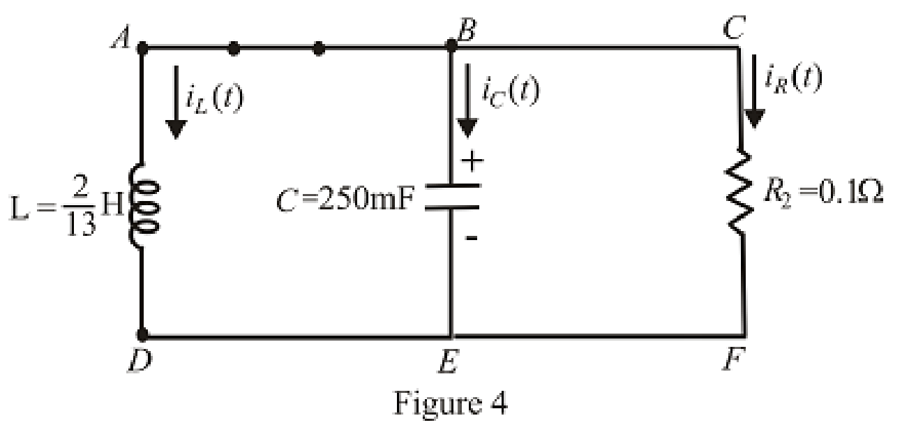
Refer to the redrawn Figure 4:
Substitute
Substitute
As value of exponential frequency
Substitute
Substitute
Substitute
Substitute
Solve for
Rearrange for
Substitute
Rearrange for
Substitute
Conclusion:
Thus, the current across inductor
(b)
Find the equation for current across resistor for
Answer to Problem 13E
The equation of current
Explanation of Solution
Calculation:
Refer to the Figure 3:
The expression for current across resistor at
At
Therefore,
At
Substitute
At
Substitute
Conclusion:
Thus, the equation of current
(c)
Find the settling time for both
Answer to Problem 13E
The settling time for
Explanation of Solution
Calculation:
The settling time is the time at which current reaches to
Since the inductor current is exponential in nature and time cannot be taken as negative, therefore, inductor current takes its maximum value at
Substitute
The maximum value of current is:
The expression for current at settling time
Substitute
The settling time is the time at which the current is decreased to
Equation (24) is solved by scientific calculator which can determine the value of time
Take log both the side in equation (25).
Rearrange for
Substitute
The maximum value of current is:
The expression for current at settling time
Substitute
The settling time is the time at which the current is decreased to
The equation can be approximated for
Take log both the sides of equation (28).
Rearrange for
Conclusion:
Thus, the settling time for
Want to see more full solutions like this?
Chapter 9 Solutions
ENGINEERING CIRCUIT...(LL)>CUSTOM PKG.<
- Q1: For the circuit shown in Figure-1, (a) Calculate the equivalent resistance of the circuit, RAB at the terminals A and B. [10] (b) When 50V dc source is switched at terminals A-B, solve for the voltage V₁ at the location shown. [10] 50V www 12Ω 10Ω 5Ω www www A + B 200 Figure-1 www 10Ω ww 25Ω 100arrow_forwarda. Write a PLC ladder diagram that allows the teacher to teach AND, OR, and XOR logic gates through using three PLC's digital input points and only one digital output point.arrow_forwardrately by PRACTICE 4.2 For the circuit of Fig. 4.5, compute the voltage across each curren source. 202 ww 3A 30 ww 4Ω S 50 www Reference node FIGURE 4.5 Ans: V3A =5.235 V; 7A = 11.47 V. 7 Aarrow_forward
- Q2) a) design and show me your steps to convert the following signal from continuous form to digital form: s(t)=3sin(3πt) -1 373 Colesarrow_forwardA sequence is defined by the relationship r[n] = [h[m]h[n+m]=hn*h-n where h[n] is a minimum-phase sequence and r[n]= 4 4 (u[n]+ 12" [n-1] 3 (a) Find R(z) and sketch the pole-zero diagram. (b) Determine the minimum-phase sequence h[n] to within a scale factor of ±1. Also, determine the z-transform H(z) of h[n].arrow_forwardusıng j-k and D flipflop design a counter that counts 0,2,1 again as shown below ın the tablearrow_forward
- find the minterms of the followıng boolean expressıon desıgn F's cırcuit using one of the approciate decoders given below and a NOR gateF(A,B,C,D)=(A+'BC)(B 'C+'A 'D + CD)arrow_forward64) answer just two from three the following terms: A) Design ADC using the successive method if the Vmax=(3) volt, Vmin=(-2) volt, demonstrate the designing system for vin-1.2 volt. Successive Approximation ADC Input Voltage-1.1 V -4-3.5-3 -2.5 -2 -1.5 +1 -0.5 0 0.5 1 1.5 2 2.5 3 3.5 1 T -8 -7 -6 -5 -3 +2 -1 0 1 2 3 4 5 6 7 X=1??? 1st guess: -0.25 V (too high) X=11?? 2nd guess: -2.25 V (too low) 3rd guess: -1.25 V (too low) X=1110 X=111? 4th guess: -0.75 V (too high) Make successive guesses and use a comparator to tell whether your guess is too high or too low. Each guess determines one bit of the answer and cuts the number of remaining possibilities in half.arrow_forwardDatacommunıcatıonin a commuinaction ASYNCHRONOUS TRANSMİTİON is used in this transmistion 7-bit chatacter will be transfered even parity will be used ,stop element is as 1,5 bits a)=select a chracter yourself and dısplay the signal transfered in this transmission , and calculate the overhead in this transmisionarrow_forward
- (i) Find the inverse z-transform of the system H(z) = for the following regions of convergence. Write in the final answer for each case in the allocated rectangular box below (a) |z| 3 (c) 1arrow_forwardQ3: Material A and Material B are collected in a tank as shown where the system consists of three Push-Button, three Level Sensors, two Inlet valve, one Outlet valve, Heater, Temperature Sensor, Agitator Motor, and Alarm Light. Material A and Material B are to be mixed and heated until it reaches 90°C temperature, and it will be drain using outlet valve also high-level Alarm Light will come ON when the tank is full and stay on even if the tank level drops until the operator press Reset Push-Button. Implement automation of this system in PLC using Ladder Diagram programming language (Note: The tank is fed with Material A before B and the temperature sensor can withstand 200°C and it gives voltage from 0 to 10 volts) (25 Marks) Valve A Agitator Motor Valve B Level B Heater E Level A Low Level Sta Start Push-Button Stop Push-Button 36. ویر نکند Temperature sensor Outlet Valve Reset Push-Button Alarm Lightarrow_forward.Explain how a gated J-K latch operates differently from an edge-triggered J-K flip-flop. . For the gated T Latch circuit, answer the following: a) Draw the gate-level diagram of a gated T latch using basic logic gates and SR latch b) Write the characteristic equation. c) Draw the state diagram.arrow_forwardarrow_back_iosSEE MORE QUESTIONSarrow_forward_ios
 Introductory Circuit Analysis (13th Edition)Electrical EngineeringISBN:9780133923605Author:Robert L. BoylestadPublisher:PEARSON
 Delmar's Standard Textbook Of ElectricityElectrical EngineeringISBN:9781337900348Author:Stephen L. HermanPublisher:Cengage Learning
 Programmable Logic ControllersElectrical EngineeringISBN:9780073373843Author:Frank D. PetruzellaPublisher:McGraw-Hill Education
 Fundamentals of Electric CircuitsElectrical EngineeringISBN:9780078028229Author:Charles K Alexander, Matthew SadikuPublisher:McGraw-Hill Education
 Electric Circuits. (11th Edition)Electrical EngineeringISBN:9780134746968Author:James W. Nilsson, Susan RiedelPublisher:PEARSON
 Engineering ElectromagneticsElectrical EngineeringISBN:9780078028151Author:Hayt, William H. (william Hart), Jr, BUCK, John A.Publisher:Mcgraw-hill Education,


