
Concept explainers
Videos
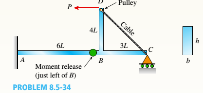
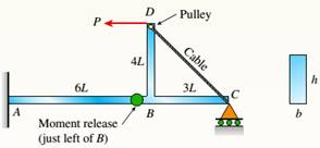
A compound beam ABCD has a cable with force P anchored at C The cable passes over a pulley at D, and force P acts in the —x direction, There is a moment release just left of B. Neglect the self-weight of the beam and cable. Cable force P = 450 N and dimension variable L = 0.25 m. The beam has a rectangular cross section (b = 20 mm, it = 50 mm).
(a) Calculate the maximum normal stresses and maximum in-plane shear stress on the bottom surface of the beam at support A.
(b) Repeat part (a) for a plane stress element located at mid-height of the beam at A.
(c) If the maximum tensile stress and maximum in-plane shear stress at point A are limited to 90 MPa and 42 MPa, respectively, what is the largest permissible value of the cable force P?
(a)
The maximum normal stresses and maximum in-plane shear stress on the bottom of the beam at fixed support A.
Answer to Problem 8.5.34P
Maximum normal stresses,
Maximum in-plane shear stress
Explanation of Solution
Given information: A compound beam ABCD has a cable having force P anchored at C as shown in the figure below:
Cable force
Dimension variable
The cross section of the beam
To calculate the maximum normal stress and in-plane shear stress first taken the cross-sectional properties of the beam.
Area of the rectangular beam
Moment of inertia of the rectangular beam is
Now reactions at fixed support A
Horizontal force
Shear force
And moment at point A,
Now, maximum normal stresses on the bottom of the beam at A is,
And at principle plane where there is maximum normal stress the shear stress is zero. So,
Principle stresses:
Maximum in-plane shear stress
(b)
Maximum stresses located at the mid-height of the beam at A.
Answer to Problem 8.5.34P
Maximum normal stresses,
Maximum in-plane shear stress
Explanation of Solution
Given information: A compound beam ABCD has a cable having force P anchored at C as shown in the figure below:

Cable force
Dimension variable
The cross section of the beam
Area of the rectangular beam
Moment of inertia of the rectangular beam is
Now reactions at fixed support A
Horizontal force
Shear force
The maximum normal stresses at the mid-point of the beam at A is,
And,
Principle stresses:
Maximum in-plane shear stress
(c)
The maximum permissible value of the cable force P.
Answer to Problem 8.5.34P
Maximum permissible value of P
Explanation of Solution
Given information: A compound beam ABCD has a cable having force P anchored at C as shown in the figure below:

Dimension variable
Maximum tensile stress at point A,
Maximum shear stress at point A,
The cross section of the beam
Area of the rectangular beam
Moment of inertia of the rectangular beam is
And moment at point A,
In the above figure the maximum cable force P is controlled by the tensile and maximum shear force at the bottom of the beam at point A.
Hence, tensile stress
Then,
By substituting the values we get,
And,
Then,
Conclusion:
Hence from the obtained values the maximum permissible value of the force P is
Want to see more full solutions like this?
Chapter 8 Solutions
Mechanics of Materials (MindTap Course List)


- 1. The maximum and minimum stresses as well as the shear stress seen subjected the piece in plane A-A. Assume it is a cylinder with a diameter of 12.7mm 2. Draw the Mohr circle for the stress state using software. 3. Selection of the material for the prosthesis, which must be analyzed from the point of safety and cost view.arrow_forwardFirst, define the coordinate system XY with its origin at O2 and X-axis passing through O4 asshown above, then based on the provided steps Perform coordinate transformation from XY to xy to get the trajectory of point P. Show all the steps and calcualtionsarrow_forwardI don't know how to solve thisarrow_forward
- Question 2 (40 Points) Consider the following double pendulum-like system with links ₁ and 12. The angles 0 and & could have angular velocities ėêk and êk, respectively, where ②k is a unit vector that points out of the page and is perpendicular to x and y. They could also have angular accelerations Ök and êk. The angle is defined relative to the angle 0. The link 12 is a spring and can extend or compress at a rate of 12. It can also have a rate of extension or compression Ï2. li y êr1 êe 12 χ 3 еф er2 ده لج 1) Express the velocity of the mass in terms of the unit vectors ê0, êr1, êø, and êr2, and any extension/contraction of the links (e.g.,. i; and Ï¿) (12 Points) 2) Express the acceleration of the mass in terms of the unit vectors ê¤, ê×1, êp, and êÃ2, and any extension/contraction of the links (e.g.,. İ; and Ï¿) (12 Points) 3) Express the velocity of the mass in terms of unit vectors î and ĵ that point in the x and y directions, respectively. Also include the appropriate,…arrow_forwardprovide step by step solutions for angles teta 3 and teta 4 by the vector loopmethod. Show work in: vector loop, vector equations, solution procedure.arrow_forward(Manometer) A tank is constructed of a series of cylinders having diameters of 0.35, 0.30, and 0.20 m as shown in the figure below. The tank contains oil, water, and glycerin and a mercury manometer is attached to the bottom as illustrated. Calculate the manometer reading, h. 0.11 m + SAE 30 Oil 0.13 m + Water 0.10 m Glycerin + 0.10 m Mercury h = marrow_forward
- P = A piston having a cross-sectional area of 0.40 m² is located in a cylinder containing water as shown in the figure below. An open U-tube manometer is connected to the cylinder as shown. For h₁ = 83 mm and h = 111 mm what is the value of the applied force, P, acting on the piston? The weight of the piston is negligible. Hi 5597.97 N P Piston Water Mercuryarrow_forwardStudent Name: Student Id: College of Applied Engineering Al-Muzahmiyah Branch Statics (AGE 1330) Section-1483 Quiz-2 Time: 20 minutes Date: 16/02/2025 Q.1. A swinging door that weighs w=400.0N is supported by hinges A and B so that the door can swing about a vertical' axis passing through the hinges (as shown in below figure). The door has a width of b=1.00m and the door slab has a uniform mass density. The hinges are placed symmetrically at the door's edge in such a way that the door's weight is evenly distributed between them. The hinges are separated by distance a=2.00m. Find the forces on the hinges when the door rests half-open. Draw Free body diagram also. [5 marks] [CLO 1.2] Mool b ర a 2.0 m B 1.0 marrow_forwardFor the walking-beam mechanism shown in Figure 3, find and plot the x and y coordinates of the position of the coupler point P for one complete revolution of the crank O2A. Use the coordinate system shown in Figure 3. Hint: Calculate them first with respect to the ground link 0204 and then transform them into the global XY coordinate system. y -1.75 Ꮎ Ꮎ 4 = 2.33 0242.22 L4 x AP = 3.06 L2 = 1.0 W2 31° B 03 L3 = 2.06 P 1 8 5 .06 6 7 P'arrow_forward
- The link lengths, gear ratio (2), phase angle (Ø), and the value of 02 for some geared five bar linkages are defined in Table 2. The linkage configuration and terminology are shown in Figure 2. For the rows assigned, find all possible solutions for angles 03 and 04 by the vector loop method. Show your work in details: vector loop, vector equations, solution procedure. Table 2 Row Link 1 Link 2 Link 3 Link 4 Link 5 λ Φ Ө a 6 1 7 9 4 2 30° 60° P y 4 YA B b R4 R3 YA A Gear ratio: a 02 d 05 r5 R5 R2 Phase angle: = 0₂-202 R1 05 02 r2 Figure 2. 04 Xarrow_forwardProblem 4 A .025 lb bullet C is fired at end B of the 15-lb slender bar AB. The bar is initially at rest, and the initial velocity of the bullet is 1500 ft/s as shown. Assuming that the bullet becomes embedded in the bar, find (a) the angular velocity @2 of the bar immediately after impact, and (b) the percentage loss of kinetic energy as a result of the impact. (c) After the impact, does the bar swing up 90° and reach the horizontal? If it does, what is its angular velocity at this point? Answers: (a). @2=1.6 rad/s; (b). 99.6% loss = (c). Ah2 0.212 ft. The bar does not reach horizontal. y X 4 ft 15 lb V₁ 1500 ft/s 0.025 lb C 30°7 B Aarrow_forwardsubject: combustion please include complete solution, no rounding off, with diagram/explanation etc. In a joule cycle, intake of the compressor is 40,000 cfm at 0.3 psig and 90 deg F. The compression ratio is 6.0 and the inlet temperature at the turbine portion is 1900R while at the exit, it is 15 psi. Calculate for the back work ratio in percent.arrow_forward
 Mechanics of Materials (MindTap Course List)Mechanical EngineeringISBN:9781337093347Author:Barry J. Goodno, James M. GerePublisher:Cengage Learning