
Concept explainers
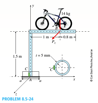
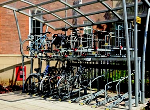
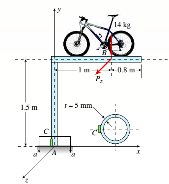
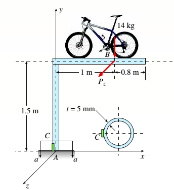
Repeat Problem 8.5-22 but replace the square tube column with a circular tube having a wall thickness r = 5 mm and the same cross-sectional area (3900 mm2) as that of the square tube in figure b in Problem 8.5-22. Also, add force P. = 120 N at B
(a) Find the state of plane stress at C. (b) Find maximum normal stresses and show them on a sketch of a properly oriented element.
(c) Find maximum shear stresses and show them on a sketch of a properly oriented element.
(a)
The state of plane stress on an element C.
Answer to Problem 8.5.24P
The state of stress on element C are
Tensile stress
Compressive stress
Explanation of Solution
Given information:
The cross-section of the bicycle rack tubing is circular.
The weight of the bicycle = 14 kg is represented as point load applied at B on a plane frame model of the rack.
A force in z direction has also been added Pz= 120 N
Weight density of the steel
Calculation:
From the figure, let us consider horizontal portion of the cycle rack. The weight of the cycle is considered as the point load and this load produces a moment and a direct compressive load in the beam along Y-direction.
Also, a load Pzhas been added in z direction. This load will produce bending moment in the horizontal beam and twisting moment in the vertical portion of the beam.
The cross-sectional area of the beam is given by
The moment in the vertical beam =
The moment in the horizontal beam due to load Pz=
Total moment
The load Pzwill produce twisting moment equal to Mz. This twisting moment will produce the shear stress at the base of rack.
The direct compressive loading =
From the properties of the cross-section, the moment of inertia is
Now, plane stress can be calculated as follows
And maximum compressive stress is
Conclusion: Thus, the state of stress on element C are
Tensile stress
Compressive stress
(b)
The maximum normal stress and the sketch of properly oriented element.
Answer to Problem 8.5.24P
The normal stress values on element C are,
Explanation of Solution
Given information:
The cross-section of the bicycle rack tubing is circular.
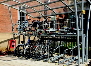
The weight of the bicycle = 14 kg is represented as point load applied at B on a plane frame model of the rack.
A force in z direction has also been added Pz= 120 N
Weight density of the steel
Calculation:
From the figure, let us consider horizontal portion of the cycle rack. The weight of the cycle is considered as the point load and this load produces a moment and a direct compressive load in the beam along Y-direction.
Also, a load Pzhas been added in z direction. This load will produce bending moment in the horizontal beam and twisting moment in the vertical portion of the beam.
The cross-sectional area of the beam is given by
The moment in the vertical beam =
The moment in the horizontal beam due to load Pz=
Total moment
The load Pzwill produce twisting moment equal to Mz. This twisting moment will produce the shear stress at the base of rack.
The direct compressive loading =
From the properties of the cross-section, the moment of inertia is
Now, plane stress can be calculated as follows
And maximum compressive stress is
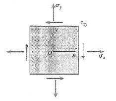
The shear stress on the element is given by the torque and shear stress relation.
The normal stresses are given by
And,
The state of stress on the element can be shown as follows
Conclusion: Thus, the normal stress values on element C are,
(c)
The maximum shear stress and the sketch of properly oriented element.
Answer to Problem 8.5.24P
the maximum stress values on element C is
Explanation of Solution
Given information:
The cross-section of the bicycle rack tubing is circular.
The weight of the bicycle = 14 kg is represented as point load applied at B on a plane frame model of the rack.
A force in z direction has also been added Pz= 120 N
Weight density of the steel
Calculation:
From the figure, let us consider horizontal portion of the cycle rack. The weight of the cycle is considered as the point load and this load produces a moment and a direct compressive load in the beam along Y-direction.
Also, a load Pzhas been added in z direction. This load will produce bending moment in the horizontal beam and twisting moment in the vertical portion of the beam.
The cross-sectional area of the beam is given by
The moment in the vertical beam =
The moment in the horizontal beam due to load Pz=
Total moment
The load Pzwill produce twisting moment equal to Mz. This twisting moment will produce the shear stress at the base of rack.
The direct compressive loading =
From the properties of the cross-section, the moment of inertia is
Now, plane stress can be calculated as follows
And maximum compressive stress is
The shear stress on the element is given by the torque and shear stress relation.
The normal stresses are given by
And,
The in plane maximum shear stress value is given by
The state of stress on the element can be shown as follows
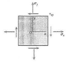
Conclusion: Thus, the maximum stress values on element C is
Want to see more full solutions like this?
Chapter 8 Solutions
Mechanics of Materials (MindTap Course List)
- The differential equation of a cruise control system is provided by the following equation: Find the closed loop transfer function with respect to the reference velocity (vr) . a. Find the poles of the closed loop transfer function for different values of K. How does the poles move as you change K? b. Find the step response for different values of K and plot in MATLAB. What can you observe? c. For the given transfer function, find tp, ts, tr, Mp . Plot the resulting step response. G(s) = 40/(s^2 + 4s + 40)arrow_forwardAuto Controls Perform the partial fraction expansion of the following transfer function and find the impulse response: G(s) = (s/2 + 5/3) / (s^2 + 4s + 6) G(s) =( 6s^2 + 50) / (s+3)(s^2 +4)arrow_forwardStudy Area Document Sharing User Settings mylabmastering.pearson.com Access Pearson P Pearson MyLab and Mastering The 150-lb skater passes point A with a speed of 6 ft/s. (Figure 1) Figure 1 of 1 Part A P Course Home b My Questions | bartleby Determine his speed when he reaches point B. Neglect friction. Express your answer to three significant figures and include the appropriate units. με ? VB = Value Units Submit Request Answer Part B Determine the normal force exerted on him by the track at this point. Express your answer to three significant figures and include the appropriate units. ☐ о Α NB = Value Units Submit Request Answer Provide Feedback ? ■Review Next >arrow_forward
- mylabmastering.pearson.com Access Pearson P Pearson MyLab and Mastering P Course Home b My Questions | bartleby Study Area Document Sharing User Settings The 100-kg crate is subjected to the forces shown. The crate is originally at rest. The coefficient of kinetic friction between the crate and the surface is μk = 0.2. (Figure 1) Part A Determine the distance it slides in order to attain a speed of 8.1 m/s. Express your answer to three significant figures and include the appropriate units. Figure 500 N 1 of 1 Α S = Value Units Submit Request Answer Provide Feedback ? ■Review Next >arrow_forwardThe differential equation of a DC motor can be described by the following equation Find the transfer function between the applied voltage ( Va)and the motor speed (thetadot m). What is the steady state speed of the motor after a voltage (Va = 10V) has been applied. Find the transfer function between the applied voltage (Va) and the shaft angle (thetadot m) .arrow_forwardStudy Area Document Sharing User Settings Access Pearson mylabmastering.pearson.com P Pearson MyLab and Mastering The crash cushion for a highway barrier consists of a nest of barrels filled with an impact-absorbing material. The barrier stopping force is measured versus the vehicle penetration into the barrier. (Figure 1) Part A P Course Home b My Questions | bartleby Review Determine the distance a car having a weight of 4000 lb will penetrate the barrier if it is originally traveling at 55 ft/s when it strikes the first barrel. Express your answer to three significant figures and include the appropriate units. Figure 1 of 1 36 μΑ S = Value Units Submit Request Answer Provide Feedback ? Next >arrow_forward
- Study Area Document Sharing User Settings mylabmastering.pearson.com Access Pearson P Pearson MyLab and Mastering Part A P Course Home b My Questions | bartleby ■Review The sports car has a mass of 2.5 Mg and accelerates at 6 m/s², starting from rest. (Figure 1) If the drag resistance on the car due to the wind is FD = (10v) N, where v is the velocity in m/s, determine the power supplied to the engine when t = 5 s. The engine has a running efficiency of € = 0.66. Express your answer to three significant figures and include the appropriate units. Figure 1 of 1 о Α ? P = Value Units Submit Request Answer Return to Assignment Provide Feedbackarrow_forwardAccess Pearson Study Area mylabmastering.pearson.com P Pearson MyLab and Mastering Document Sharing User Settings The car in (Figure 1) having a mass of 2 Mg is originally traveling at 2 m/s. Assume 0 = 22°. Figure 1 of 1 Part A P Course Home b My Questions | bartleby ■Review Determine the distance it must be towed by a force F = 4 kN in order to attain a speed of 6 m/s. Neglect friction and the mass of the wheels. Express your answer to three significant figures and include the appropriate units. Α ? S = Value Units Submit Request Answer Provide Feedback Next >arrow_forwardDerive the Laplace transform of the following functions. Use the definition of Laplace transform. f(t)=sin4t and f(t)=cos2t Auto Controlsarrow_forward
- Study Area Document Sharing User Settings Access Pearson P Pearson MyLab and Mastering Marbles having a mass of 5 g fall from rest at A through the glass tube and accumulate in the can at C. (Figure 1) Figure Aarrow_forwardVC Vc B S TDC -BDC S TQ Tp = Pg A (asne) [1+ % CUSA] At what position (in degrees after top dead center) would you want the peak pressure of combustion to occur to create the maximum torque on the crankshaft? For a 100mm piston digimeter acting on a connecting. rod with a length of 80mm use the equation above to calculate the torque (NIM) on the crankshaft at this crank position for an engine that develops a peak pressure of 135 bararrow_forwardAccess Pearson P Pearson MyLab and Mastering Study Area Document Sharing User Settings The man having a weight of 180 lb is able to run up a 18-ft-high flight of stairs shiwn in (Figure 1) in 4 s. Figure 1 of 1 R mylabmastering.pearson.com Part A P Course Home b My Questions | bartleby Determine the power generated. Express your answer in horsepower to three significant figures. ΜΕ ΑΣΦ. Η vec P = Submit Request Answer Part B ? hp How long would a 100-W light bulb have to burn to expend the same amount of energy? Express your answer to three significant figures and include the appropriate units. HÅ ? t = Value Units Submit Request Answer Provide Feedback Review Next >arrow_forward
 Mechanics of Materials (MindTap Course List)Mechanical EngineeringISBN:9781337093347Author:Barry J. Goodno, James M. GerePublisher:Cengage Learning
