
EBK FUNDAMENTALS OF ELECTRIC CIRCUITS
6th Edition
ISBN: 8220102801448
Author: Alexander
Publisher: YUZU
expand_more
expand_more
format_list_bulleted
Concept explainers
Videos
Textbook Question
Chapter 7, Problem 48P
Find v(t) and i(t) in the circuit of Fig. 7.115.
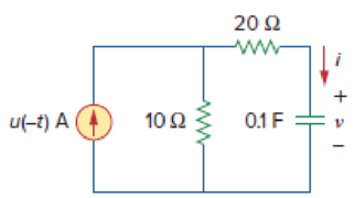
Figure 7.115
Expert Solution & Answer
Want to see the full answer?
Check out a sample textbook solution
Students have asked these similar questions
Solve this problem and show all of the work
The joint probability density function of two discrete random variables X and
Y is given by p(x, y)=c(2x+y), where x and y can assume all integers such that 0≤
x≤2, 0≤ y ≤ 3, and p (x, y)= 0 otherwise. a) Find the value of the constant c. (c)
Find P(X≥1, Y≤2). (b) Find P(X=2, Y= 1).
A wattmeter is connected with the positive lead on phase "a" of a three-phase system. The negative lead
is connected to phase "b". A separate wattmeter has the positive lead connected to phase "c". The
negative lead of this wattmeter is connected also to phase "b". If the input voltage is 208 volts line-to-
line, the phase sequence is "abc" and the load is 1200 ohm resistors connected in "Y", what is the
expected reading of each of the wattmeters? (Hint: draw a phasor diagram)
Chapter 7 Solutions
EBK FUNDAMENTALS OF ELECTRIC CIRCUITS
Ch. 7.2 - Refer to the circuit in Fig. 7.7. Let vC (0) = 60...Ch. 7.2 - If the switch in Fig. 7.10 opens at t = 0, find...Ch. 7.3 - Find i and vx in the circuit of Fig. 7.15. Let...Ch. 7.3 - For the circuit in Fig. 7.18, find i(t) for t 0....Ch. 7.3 - Determine i, io, and vo for all t in the circuit...Ch. 7.4 - Express the current pulse in Fig. 7.33 in terms of...Ch. 7.4 - Refer to Fig. 7.39. Express i(t) in terms of...Ch. 7.4 - If h t = 0, t0 4, 0t2 3t8, 2t6 0, t6 express h(t)...Ch. 7.4 - Practice Problem 7.9 Evaluate the following...Ch. 7.5 - Find v(t) for t 0 in the circuit of Fig. 7.44....
Ch. 7.5 - The switch in Fig. 7.47 is closed at t = 0. Find...Ch. 7.6 - The switch in Fig. 7.52 has been closed for a long...Ch. 7.6 - Switch S1 in Fig. 7.54 is closed at t = 0, and...Ch. 7.7 - For the op amp circuit in Fig. 7.56, find vo for t...Ch. 7.7 - Find v(t) and vo(t) in the op amp circuit of Fig....Ch. 7.7 - Obtain the step response vo(t) for the circuit in...Ch. 7.8 - For the circuit in Fig. 7.66, use Pspice to find...Ch. 7.8 - The switch in Fig. 7.71 was open for a long time...Ch. 7.9 - The RC circuit in Fig. 7.74 is designed to operate...Ch. 7.9 - The flash unit of a camera has a 2-mF capacitor...Ch. 7.9 - A relay has a resistance of 200 and an inductance...Ch. 7.9 - Prob. 22PPCh. 7 - An RC circuit has R = 2 and C = 4 F. The time...Ch. 7 - The time constant for an RL circuit with R = 2 ...Ch. 7 - A capacitor in an RC circuit with R = 2 and C = 4...Ch. 7 - An RL circuit has R = 2 and L = 4 H. The time...Ch. 7 - In the circuit of Fig. 7.79, the capacitor voltage...Ch. 7 - Figure 7.79 For Review Questions 7.5 and 7.6....Ch. 7 - For the circuit in Fig. 7.80, the inductor current...Ch. 7 - Figure 7.80 For Review Questions 7.7 and 7.8....Ch. 7 - If vs changes from 2 V to 4 V at t = 0, we may...Ch. 7 - The pulse in Fig. 7.116(a) can be expressed in...Ch. 7 - In the circuit shown in Fig. 7.81...Ch. 7 - Find the time constant for the RC circuit in Fig....Ch. 7 - Determine the time constant for the circuit in...Ch. 7 - The switch in Fig. 7.84 has been in position A for...Ch. 7 - Using Fig. 7.85, design a problem to help other...Ch. 7 - The switch in Fig. 7.86 has been closed for a long...Ch. 7 - Assuming that the switch in Fig. 7.87 has been in...Ch. 7 - For the circuit in Fig. 7.88, if...Ch. 7 - The switch in Fig. 7.89 opens at t = 0. Find vo...Ch. 7 - For the circuit in Fig. 7.90, find vo(t) for t 0....Ch. 7 - For the circuit in Fig. 7.91, find io for t 0....Ch. 7 - Using Fig. 7.92, design a problem to help other...Ch. 7 - In the circuit of Fig. 7.93,...Ch. 7 - Calculate the time constant of the circuit in Fig....Ch. 7 - Find the time constant for each of the circuits in...Ch. 7 - Determine the time constant for each of the...Ch. 7 - Consider the circuit of Fig. 7.97. Find vo(t) if...Ch. 7 - For the circuit in Fig. 7.98, determine vo(t) when...Ch. 7 - In the circuit of Fig. 7.99, find i(t) for t 0 if...Ch. 7 - For the circuit in Fig. 7.100, v = 90e50t V and i...Ch. 7 - In the circuit of Fig. 7.101, find the value of R...Ch. 7 - Find i(t) and v(t) for t 0 in the circuit of Fig....Ch. 7 - Consider the circuit in Fig. 7.103. Given that...Ch. 7 - Express the following signals in terms of...Ch. 7 - Design a problem to help other students better...Ch. 7 - Express the signals in Fig. 7.104 in terms of...Ch. 7 - Express v(t) in Fig. 7.105 in terms of step...Ch. 7 - Sketch the waveform represented by i(t) = [r(t) ...Ch. 7 - Sketch the following functions: (a) x(t) = 10etu(t...Ch. 7 - Prob. 30PCh. 7 - Evaluate the following integrals: (a)e4t2(t2)dt...Ch. 7 - Prob. 32PCh. 7 - The voltage across a 10-mH inductor is 45(t 2)mV....Ch. 7 - Evaluate the following derivatives: (a) ddtut1ut+1...Ch. 7 - Find the solution to the following differential...Ch. 7 - Solve for v in the following differential...Ch. 7 - A circuit is described by 4dvdt+v=10 (a) What is...Ch. 7 - A circuit is described by didt+3i=2ut Find i(t)...Ch. 7 - Calculate the capacitor voltage for t 0 and t 0...Ch. 7 - Find the capacitor voltage for t 0 and t 0 for...Ch. 7 - Using Fig. 7.108, design a problem to help other...Ch. 7 - (a) If the switch in Fig. 7.109 has been open for...Ch. 7 - Consider the circuit in Fig. 7.110. Find i(t) for...Ch. 7 - The switch in Fig. 7.111 has been in position a...Ch. 7 - Find vo in the circuit of Fig. 7.112 when vs =...Ch. 7 - Prob. 46PCh. 7 - Determine v(t) for t 0 in the circuit of Fig....Ch. 7 - Find v(t) and i(t) in the circuit of Fig. 7.115....Ch. 7 - If the waveform in Fig. 7.116(a) is applied to the...Ch. 7 - In the circuit of Fig. 7.117, find ix for t 0....Ch. 7 - Rather than applying the shortcut technique used...Ch. 7 - Using Fig. 7.118, design a problem to help other...Ch. 7 - Determine the inductor current i(t) for both t 0...Ch. 7 - Obtain the inductor current for both t 0 and t 0...Ch. 7 - Find v(t) for t 0 and t 0 in the circuit of Fig....Ch. 7 - Prob. 56PCh. 7 - Prob. 57PCh. 7 - Rework Prob. 7.17 if i(0) = 10 A and v(t) = 20u(t)...Ch. 7 - Determine the step response vo(t) to is = 6u(t) A...Ch. 7 - Find v(t) for t 0 in the circuit of Fig. 7.125 if...Ch. 7 - In the circuit in Fig. 7.126, is changes from 5 A...Ch. 7 - For the circuit in Fig. 7.127, calculate i(t) if...Ch. 7 - Obtain v(t) and i(t) in the circuit of Fig. 7.128....Ch. 7 - Determine the value of iL(t) and the total energy...Ch. 7 - If the input pulse in Fig. 7.130(a) is applied to...Ch. 7 - Using Fig. 7.131, design a problem to help other...Ch. 7 - If v(0) = 10 V, find vo(t) for t 0 in the op amp...Ch. 7 - Prob. 68PCh. 7 - For the op amp circuit in Fig. 7.134, find vo(t)...Ch. 7 - Determine vo for t 0 when vs = 20 mV in the op...Ch. 7 - For the op amp circuit in Fig. 7.136, suppose vs =...Ch. 7 - Find io in the op amp circuit in Fig. 7.137....Ch. 7 - For the op amp circuit of Fig. 7.138, let R1 = 10...Ch. 7 - Determine vo(t) for t 0 in the circuit of Fig....Ch. 7 - In the circuit of Fig. 7.140, find vo and io,...Ch. 7 - Repeat Prob. 7.49 using PSpice or MultiSim. If the...Ch. 7 - The switch in Fig. 7.141 opens at t = 0. Use...Ch. 7 - The switch in Fig. 7.142 moves from position a to...Ch. 7 - In the circuit of Fig. 7.143, determine io(t)....Ch. 7 - In the circuit of Fig. 7.144, find the value of io...Ch. 7 - Repeat Prob. 7.65 using PSpice or MultiSim. If the...Ch. 7 - In designing a signal-switching circuit, it was...Ch. 7 - Prob. 83PCh. 7 - A capacitor with a value of 10 mF has a leakage...Ch. 7 - A simple relaxation oscillator circuit is shown in...Ch. 7 - Figure 7.146 shows a circuit for setting the...Ch. 7 - A 120-V dc generator energizes a motor whose coil...Ch. 7 - The circuit in Fig. 7.148(a) can be designed as an...Ch. 7 - An RL circuit may be used as a differentiator if...Ch. 7 - An attenuator probe employed with oscilloscopes...Ch. 7 - The circuit in Fig. 7.150 is used by a biology...Ch. 7 - To move a spot of a cathode-ray tube across the...
Knowledge Booster


Learn more about
Need a deep-dive on the concept behind this application? Look no further. Learn more about this topic, electrical-engineering and related others by exploring similar questions and additional content below.Similar questions
- 1- Write the mesh equation for the circuit below. Solve the equations using Crame method (matrix and determinant), and find the current of resistor 4 ohm. 6 A www 10 Ω w 6Ω www 12 V + 402 www 12 Ω 2- Write the nodal equations for the circuit below. You do not need to solve the equation just write the matrix equation. R3 ww 8Ω R₁ 201 5 A 12 3A R₂40arrow_forwardPlease solve these 3 questions in detailarrow_forward1. Please draw the root locus by hand for the following closed-loop system, where G(s) s+8 S-2 and H(s) = Find the range of K for stability Input R(s) Output C(s) KG(s) H(s) s+6 = S-2arrow_forward
- The state-space Jordan Canonical Form of the following system is: Y(s) 8-5 U(s) (+1)(+3) Select one: O a. -1 0 0 A = 0 -1 0 B: ... ... ... 0 0 C [4 1.5 1.5], D=0 b. -3 1 0 0 A = 0 -3 0 1 B ... 0 0 -1 C -4 -1.5 1.5], D=0 ○ C. -3 1 0 A = 0 -3 0 1 ,B= ... 0 0 ○ d. C [4 1.5 1.5], D=0 -3 1 0 0 A = 0 -3 0 1 , B: ... ... 0 0 -1 C [4 1.5 1.5], D=0 -4 1 If= x and (0): = then 2(t) is: -4 0 Select one: a. x2(t)=4te2t O b. x2(t) = e2t+2te2t Oc. 2(t)=-4te-21 Od. 2(t) e2-2te-2 =arrow_forwardThree speech signals are TDM multiplexed with a high-quanty music signal. It each speech signal is sampled at 16 kHz and PCM quantized by 8 bits/sample, while the music signal is sampled at 64 kHz with the same PCM quantizer. 1. Draw the block diagram of this TDM. 2. Calculate the output bit rate of this TDM.arrow_forward3- For the network below determine the value of R for maximum power to R (use Thevenin equivalent) and determine the value of maximum power R₁ 1.2Ω E + 12 V I D 10 A R₂60 6Ω Rarrow_forward
- Please solve this problem in detail to understandarrow_forwardQ3: (40 Marks) Single phase full bridge voltage source inverter has an RLC load with R-1002, L-31.5mH and C=112µF. The inverter frequency is 60Hz and de input voltage is 220V. (a) Express the instantaneous load current in Fourier series to third harmonic. (b) Calculate the RMS load current at the fundamental frequency (n=1). (c) Calculate the load power due to fundamental component (n=1).arrow_forward12.3 Express each of the waveforms in Fig. P12.3 (on page 667) in terms of step functions and then determine its Laplace transform. [Recall that the ramp function is related to the step function by r(t − T) = (t − T) u(t − T).] Assume that all waveforms are zero for t<0. - - -arrow_forward
- Evaluate each of the following integraarrow_forwardWith the aid of suitable diagrams, describe the benefits that antenna arrays have over singleelement antennas, with their applicationsarrow_forwardExplain what is meant by an electric dipole antenna, sketch its radiation pattern, state itsdirectivity and describe its main applicationsarrow_forward
arrow_back_ios
SEE MORE QUESTIONS
arrow_forward_ios
Recommended textbooks for you
 Introductory Circuit Analysis (13th Edition)Electrical EngineeringISBN:9780133923605Author:Robert L. BoylestadPublisher:PEARSON
 Delmar's Standard Textbook Of ElectricityElectrical EngineeringISBN:9781337900348Author:Stephen L. HermanPublisher:Cengage Learning
 Programmable Logic ControllersElectrical EngineeringISBN:9780073373843Author:Frank D. PetruzellaPublisher:McGraw-Hill Education
 Fundamentals of Electric CircuitsElectrical EngineeringISBN:9780078028229Author:Charles K Alexander, Matthew SadikuPublisher:McGraw-Hill Education
 Electric Circuits. (11th Edition)Electrical EngineeringISBN:9780134746968Author:James W. Nilsson, Susan RiedelPublisher:PEARSON
 Engineering ElectromagneticsElectrical EngineeringISBN:9780078028151Author:Hayt, William H. (william Hart), Jr, BUCK, John A.Publisher:Mcgraw-hill Education,
Introductory Circuit Analysis (13th Edition)
Electrical Engineering
ISBN:9780133923605
Author:Robert L. Boylestad
Publisher:PEARSON
Delmar's Standard Textbook Of Electricity
Electrical Engineering
ISBN:9781337900348
Author:Stephen L. Herman
Publisher:Cengage Learning
Programmable Logic Controllers
Electrical Engineering
ISBN:9780073373843
Author:Frank D. Petruzella
Publisher:McGraw-Hill Education
Fundamentals of Electric Circuits
Electrical Engineering
ISBN:9780078028229
Author:Charles K Alexander, Matthew Sadiku
Publisher:McGraw-Hill Education
Electric Circuits. (11th Edition)
Electrical Engineering
ISBN:9780134746968
Author:James W. Nilsson, Susan Riedel
Publisher:PEARSON
Engineering Electromagnetics
Electrical Engineering
ISBN:9780078028151
Author:Hayt, William H. (william Hart), Jr, BUCK, John A.
Publisher:Mcgraw-hill Education,
ENA 9.2(1)(En)(Alex) Sinusoids & Phasors - Explanation with Example 9.1 ,9.2 & PP 9.2; Author: Electrical Engineering Academy;https://www.youtube.com/watch?v=vX_LLNl-ZpU;License: Standard YouTube License, CC-BY
Electrical Engineering: Ch 10 Alternating Voltages & Phasors (8 of 82) What is a Phasor?; Author: Michel van Biezen;https://www.youtube.com/watch?v=2I1tF3ixNg0;License: Standard Youtube License