Concept explainers
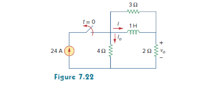
Determine i, io, and vo for all t in the circuit shown in Fig. 7.22. Assume that the switch was closed for a long time. It should be noted that opening a switch in series with an ideal current source creates an infinite voltage at the current source terminals. Clearly this is impossible. For the purposes of problem solving, we can place a shunt resistor in parallel with the source (which now makes it a voltage source in series with a resistor). In more practical circuits, devices that act likecurrent sources are, for the most part, electronic circuits. These circuits will allow the source to act like an ideal current source over its operating range but voltage-limit it when the load resistor becomes too large (as in an open circuit).

Want to see the full answer?
Check out a sample textbook solution
Chapter 7 Solutions
EBK FUNDAMENTALS OF ELECTRIC CIRCUITS
- Find a. IDQ.b. VGSQ and VDSQ.c. VD and VS.d. VDSarrow_forwardPlease answer all subpart either dislike is ready Please in typing format please ASAP Please I am again saying that all subpart is compulsory please ASAParrow_forwardUsing the Norton equivalent for the circuit shown in the following figure, determine its normal range of load current values (Fig. 7.55b). RL=50 ohms ans. = 63.17mA RL=150 ohms ans. 32.43mA (May require Thevenin Theorem or Norton Theorem) Help me to get the exact answers given..arrow_forward
- LED flashlights use "white" LEDs which have a diode voltage drop of 4.0V. A LED flashlight has the circuit illustrated and will run off several AAA batteries that have a 1.5 VDC rating. a. What is the minimum number of AAA cells needed to turn on the flashlight. b. Would you arrange the batteries in parallel or in series? Vdd R + LED V fritzingarrow_forwarddetermine:a. IDQ.b. VGSQ and VDSQ.c. VD and VS.d. VDS.arrow_forwardQuestion 7.21 Enrichment-type MOSFETFor the voltage divider configuration of Fig. 7.98, determine:a. IDQ and VGSQ.b. VD and VS.arrow_forward
- i need the answer quicklyarrow_forwardPlease answer and explain a littlearrow_forward2. For the fixed-bias configuration of Fig. 7.76, determine: a. Ip, and VGS, using a purely mathematical approach. b. Repeat part (a) using a graphical approach and compare results. c. Find VDs, VD, VG, and Vs using the results of part (a). 16 V -3 V 2.2 k2 1.2 M2 = 10 mA Ipss Vp =-4.5 V Vaso FIG. 7.76arrow_forward
- A 6.8 V Zener has a resistance of 7 Q. The actual voltage across its terminals when the Zener current is increased 30 mA is equal to O a. 6.8 V. O b. 6.59 V. O c. 210 mV. d. 7.01 V.arrow_forwardThe switch makes contact with position b just before breaking contact with position a. As already mentioned, this is known as a make-before-break switch and is designed so that the switch does not interrupt the current in an inductive circuit. The interval of time between "making" and "breaking" is assumed to be negligible. The switch has been in the a position for a long time. At t = 0 the switch is thrown from position a to position b. What percentage of the initial energy stored in the inductor is dissipated in the 90 Ω resistor 1.2 ms after the switch is thrown from position a to position b?arrow_forward1. For the network in Fig. 7.70: a. Does Is = I5 = I6? Explain. b. If Is = 10 A and I1 = 4 A, find I2. c. Does I1 + I2 = I3 + I4? Explain. d. If V2 = 8 V and E = 14 V, find V3. e. If R1 = 4 Ω, R2 = 2 Ω, R3 = 4 Ω, and R4 = 6 Ω, what is RT? f. If all the resistors of the configuration are 20 Ω, what is the source current if the applied voltage is 20 V? g. Using the values of part (f), find the power delivered by the battery and the power absorbed by the total resistance RT.arrow_forward
 Delmar's Standard Textbook Of ElectricityElectrical EngineeringISBN:9781337900348Author:Stephen L. HermanPublisher:Cengage Learning
