
Concept explainers
Videos
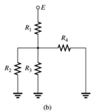
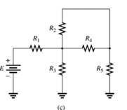
Which elements (individual elements, not combinations of elements) of the networks in Fig. 7.64. are in series? Which are in parallel? As a check on your assumptions, be sure that the elements in series have the same current and that the elements in parallel have the same voltage. Restrict your decisions to single elements not combinations of elements.
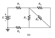
Fig 7.64
(a)
The elements of the network that are in series and in parallel.
Answer to Problem 1P
Explanation of Solution
Given:
A network is given as below.
Concept Used:
Elements in the series have the same current.
Elements in the parallels have the same voltage.
Calculation:
A network is given as below.

Since same current is flowing through
So,
Also, since same voltage is flowing through
So,
Conclusion:
Hence,
(b)
The elements of the network that are in series and in parallel.
Answer to Problem 1P
Explanation of Solution
Given:
A network is given as below.
Concept Used:
Elements in the series have the same current.
Elements in the parallels have the same voltage.
Calculation:
A network is given as below.

Since same current is flowing through
So,
And since same voltage is flowing through
So,
Conclusion:
Hence,
(c)
The elements of the network that are in series and in parallel.
Answer to Problem 1P
Explanation of Solution
Given:
A network is given as below.
Concept Used:
Elements in the series have the same current.
Elements in the parallels have the same voltage.
Calculation:
A network is given as below.

Since same current is flowing through
So,
Since same voltage is across
So,
Conclusion:
Hence,
Want to see more full solutions like this?
Chapter 7 Solutions
Introductory Circuit Analysis (13th Edition)
Additional Engineering Textbook Solutions
Starting Out with Java: From Control Structures through Data Structures (4th Edition) (What's New in Computer Science)
Introduction To Programming Using Visual Basic (11th Edition)
Starting Out with Python (4th Edition)
Degarmo's Materials And Processes In Manufacturing
Computer Science: An Overview (13th Edition) (What's New in Computer Science)
Database Concepts (8th Edition)


- Solve it in a different way than the previous solution that I searched forarrow_forwardA lossless uncharged transmission line of length L = 0.45 cm has a characteristic impedance of 60 ohms. It is driven by an ideal voltage generator producing a pulse of amplitude 10V and width 2 nS. If the transmission line is connected to a load of 200 ohms, sketch the voltage at the load as a function of time for the interval 0 < t < 20 nS. You may assume that the propagation velocity of the transmission is c/2. Answered now answer number 2. Repeat Q.1 but now assume the width of the pulse produced by the generator is 4 nS. Sketch the voltage at the load as a function of time for 0 < t < 20 nS.arrow_forwardSolve this experiment with an accurate solution, please. Thank you.arrow_forward
- A lossless uncharged transmission line of characteristic impedance Zo = 600 and length T = 1us is connected to a 180 load. If this transmission line is connected at t = 0 to a 90 V dc source with an internal resistance of 900, from a bounce diagram of this system sketch (a) the voltage at z=0, z=L, and z = L/2 for up to 7.25μs and (b) calculate the load voltage after an infinite amount of time.arrow_forwardA lossless uncharged transmission line of length L = 0.45 cm has a characteristic impedance of 60 ohms. It is driven by an ideal voltage generator producing a pulse of amplitude 10V and width 2 nS. If the transmission line is connected to a load of 200 ohms, sketch the voltage at the load as a function of time for the interval 0 < t < 20 nS. You may assume that the propagation velocity of the transmission is c/2.arrow_forwardThe VSWR (Voltage Standing Wave Ratio) is measured to be 2 on a transmission line. Find two values of the reflection coefficient with one corresponding to Z > Zo and the other to Zarrow_forwardA dc voltage of unknown value Vand internal resistance Reis connected through a switch to a lossless transmission line of Zo = 1000. If the first 5 μS of the voltages at z = 0 and z = L are observed to be as shown below, calculate Vo, RG, the load resistanceR,, and the transit time T. 100 + [V]:-0. V 90 [V]:-V 100 75 I, Տ 1,μs 2 4 6 0 2 4 6arrow_forwardA lossless open circuited transmission line behaves as an equivalent capacitance of Ceq = Tan (BL) Show for BL << 1 that Ceq = C'L where L is the length of the transmission line and wZo C' is the lumped parameter capacitance per unit length of the transmission line. Hint: For x small, Tan(x) = x.arrow_forward= A generator with VG 300V and R = 50 is connected to a load R = 750 through a 50 lossless transmission line of length L = 0.15 m. (a) Compute Zin, the input impedance of the line at the generator end. (b) Compute and V. (c) Compute the time-average power Pin delivered to the line. (d) Compute VL, IL, and the time-average power delivered to the load, PL (e) How does Pin compare to PL? Explain.arrow_forwardFor the regulated power supply circuit, assume regular diodes with 0.7V forward drop. Use a 15V (peak), 60Hz sine wave at the transformer secondary and assume a maximum ripple level of 1V. (a) Compute the unknown components needed to design 10V DC supply.Hint: find R first, and then C. What is the ripple level for C=22µF?Sketch the rectified, filtered, and regulated outputsarrow_forwardA) Find the solution of B) Find the convolution of Sewt (t-π)dt 8 e-atu(t)e-blu(t)arrow_forwardConsider the signal: f(t)= 0, ㅠ 1 Use the Fourier transform formula to find F(w). otherwisearrow_forwardarrow_back_iosSEE MORE QUESTIONSarrow_forward_ios
 Introductory Circuit Analysis (13th Edition)Electrical EngineeringISBN:9780133923605Author:Robert L. BoylestadPublisher:PEARSON
 Delmar's Standard Textbook Of ElectricityElectrical EngineeringISBN:9781337900348Author:Stephen L. HermanPublisher:Cengage Learning
 Programmable Logic ControllersElectrical EngineeringISBN:9780073373843Author:Frank D. PetruzellaPublisher:McGraw-Hill Education
 Fundamentals of Electric CircuitsElectrical EngineeringISBN:9780078028229Author:Charles K Alexander, Matthew SadikuPublisher:McGraw-Hill Education
 Electric Circuits. (11th Edition)Electrical EngineeringISBN:9780134746968Author:James W. Nilsson, Susan RiedelPublisher:PEARSON
 Engineering ElectromagneticsElectrical EngineeringISBN:9780078028151Author:Hayt, William H. (william Hart), Jr, BUCK, John A.Publisher:Mcgraw-hill Education,