
Introductory Circuit Analysis (13th Edition)
13th Edition
ISBN: 9780133923605
Author: Robert L. Boylestad
Publisher: PEARSON
expand_more
expand_more
format_list_bulleted
Concept explainers
Videos
Textbook Question
Chapter 7, Problem 14P
Find the resistance RT for the network of Fig. 7.77. Hint! If it was infinite in length, how would the resistance looking into the next vertical
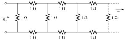
Fig. 7. 77
Expert Solution & Answer
Want to see the full answer?
Check out a sample textbook solution
Students have asked these similar questions
23ad
23aa
23ab
Chapter 7 Solutions
Introductory Circuit Analysis (13th Edition)
Ch. 7 - Which elements (individual elements, not...Ch. 7 - Repeat Problem 1 for the networks of Fig. 7.65....Ch. 7 - Determine RT for the networks in Fig. 7.66. Fig....Ch. 7 - Determine RT for the networks in Fig. 7.67. Fig....Ch. 7 - Find the total resistance for the configuration of...Ch. 7 - The total resistance RT for the network of Fig....Ch. 7 - For the network in Fig. 7.70. a. Does...Ch. 7 - For the network in Fig. 7.71: a. Determine RT. b....Ch. 7 - For the network of Fig. 7.72: a. find the currents...Ch. 7 - For the network of Fig. 7.73: Find the voltages V3...
Ch. 7 - For the network of Fig. 7.74 a. Find the voltages...Ch. 7 - For the circuit board in Fig. 7.75: Find the total...Ch. 7 - Find the value of each resistor for the network of...Ch. 7 - Find the resistance RT for the network of Fig....Ch. 7 - For the network in Fig. 7.78: a. Find currents...Ch. 7 - a. Find the magnitude and direction of the...Ch. 7 - Determine the currents I1andI2 for the network in...Ch. 7 - For the network in Fig. 7.81: a. Determine the...Ch. 7 - For the network in Fig. 7.82: a. Determine the...Ch. 7 - Determine the dc levels for the transistor network...Ch. 7 - For the network in Fig. 7.84: Determine the...Ch. 7 - For the network in Fig. 7.852 Determine RT by...Ch. 7 - For the network of Fig. 7.86: a. Find the voltages...Ch. 7 - For the network in Fig. 7.87: a. Determine the...Ch. 7 - For the network in Fig. 7.88 find the resistance...Ch. 7 - If all the resistors of the cube in Fig. 7.89 are...Ch. 7 - For the ladder network in Fig. 7.90: a. Find the...Ch. 7 - For the ladder network in Fig. 7.91: a. Determine...Ch. 7 - Given the voltage divider supply in Fig. 7.92: a....Ch. 7 - Determine the voltage divider supply resistors for...Ch. 7 - A studio lamp requires 40 V at 50 mA to burn...Ch. 7 - For the system in Fig. 7.94 a. At first exposure,...Ch. 7 - For the potentiometer in Fig. 7.95: a. What are...Ch. 7 - Prob. 34PCh. 7 - Given the voltmeter reading V = 27 V in Fig. 7.97...Ch. 7 - Determine the power delivered to the 6 load in...Ch. 7 - For the multiple ladder configuration in Fig....Ch. 7 - An iron-vane movement is rated 1 mA, 100 . a. What...Ch. 7 - Using a 50 A, 1000 movement, design a multirange...Ch. 7 - An iron-vane movement is rated 50 A , 1000 a....Ch. 7 - Using a 1 mA, 1000 movement, design a multirange...Ch. 7 - A digital meter has an internal resistance of 10 M...Ch. 7 - a. Design a series ohmmeter using a 100 A, 1000...Ch. 7 - Prob. 44PCh. 7 - Determine the reading of the ohmmeter for each...Ch. 7 - Using PSpice or Multisim, verify the result of...Ch. 7 - Using PSpice or Multisim, Confirm the solutions of...Ch. 7 - Using PSpice or Multisim, verify the result of...Ch. 7 - Using PSpice or Multisim, find voltage V6 of Fig....Ch. 7 - Using PSpice or Multisim, find voltages Vb and Vc...
Additional Engineering Textbook Solutions
Find more solutions based on key concepts
Write a summary list of the problem-solving steps identified in the chapter, using your own words.
BASIC BIOMECHANICS
CONCEPT QUESTIONS
15.CQ3 The ball rolls without slipping on the fixed surface as shown. What is the direction ...
Vector Mechanics for Engineers: Statics and Dynamics
What types of polymers are most commonly blow molded?
Degarmo's Materials And Processes In Manufacturing
How is the hydrodynamic entry length defined for flow in a pipe? Is the entry length longer in laminar or turbu...
Fluid Mechanics: Fundamentals and Applications
Consider the adage Never ask a question for which you do not want the answer. a. Is following that adage ethica...
Experiencing MIS
How does a computers main memory differ from its auxiliary memory?
Java: An Introduction to Problem Solving and Programming (8th Edition)
Knowledge Booster


Learn more about
Need a deep-dive on the concept behind this application? Look no further. Learn more about this topic, electrical-engineering and related others by exploring similar questions and additional content below.Similar questions
- c) An RC circuit is given in Figure Q1.1, where Vi(t) and Vo(t) are the input and output voltages. (i) Derive the transfer function of the circuit. (ii) With a unit step change of Vi(t) applied to the circuit, derive the time response of Vo(t) with this step change. Vi(t) C₁ Vo(1) R₂ C2 C3 | R = 20 ΚΩ = 50 ΚΩ C=C2=C3=25 μF Figure Q1.1. RC circuit.arrow_forwardc) An RC circuit is given in Figure Q1. vi(t) and vo (t) are the input and output voltages. (i) Derive the transfer function of the circuit. (ii) With a unit step change vi(t) applied to the circuit, derive and sketch the time response of the circuit. R₁ R2 v₁(t) R3 C₁ v₁(t) R₁ = R₂ = 10 k R3 = 100 kn C₁ = 100 μF Figure Q1. RC circuit.arrow_forwardc) A RC circuit is given in Figure Q1.1. Vi(t) and Vo(t) are the input and output voltages. (i) Derive the transfer function of the circuit. (ii) With a unit step change of Vi(t) applied to the circuit, derive the time response of the circuit. C₁ C₂ Vi(t) Vo(1) R₁ C₂ R-25 k C=C2=50 µF Figure Q1.1. RC circuit.arrow_forward
- Answer 2 questions for 100 marks Question 1: Process Design [25 marks] An incomplete process design of a flash drum distillation unit is presented in Figure 1. The key variables to be controlled are flow rate, temperature, composition, pressure and liquid level in the drum. Disturbances are observed in the feed temperature and composition. Heat exchangers Drum Vapor Liquid Pump Figure 1: Incomplete process design of a distillation unit Answer the following questions briefly and in a qualitative fashion: a) Determine which sensors and final elements are required so that the important variables can be controlled. Sketch them in the figure using correct instrumentation tags. Describe briefly what instruments you will use and where they should be located. Reflect on the potential presence of a flow controller upstream of your process design (not shown in the diagram). How would this affect the level controller in the drum? b) [10 marks] Describe briefly how you qualitatively determine the…arrow_forwardAnswer 2 questions for 100 marks Question 1: Process Design [25 marks] An incomplete process design of a flash drum distillation unit is presented in Figure 1. The key variables to be controlled are flow rate, temperature, composition, pressure and liquid level in the drum. Disturbances are observed in the feed temperature and composition. Heat exchangers Drum Vapor Liquid Pump Figure 1: Incomplete process design of a distillation unit Answer the following questions briefly and in a qualitative fashion: a) Determine which sensors and final elements are required so that the important variables can be controlled. Sketch them in the figure using correct instrumentation tags. Describe briefly what instruments you will use and where they should be located. Reflect on the potential presence of a flow controller upstream of your process design (not shown in the diagram). How would this affect the level controller in the drum? b) [10 marks] Describe briefly how you qualitatively determine the…arrow_forwardQuestion 2: Process Control [75 marks] As a process engineer, you are tasked to control the process shown in Figure 2. For biomedical engineers, the process could be interpreted as the injection of a solution of a medication compound A, with initial concentration CAO, into a human body, simplified as a Continuously Stirred Tank Reactor (CSTR). Therefore, your task is to analyse and model this process. The equipment consists of a mixing tank, mixing pipe and CSTR. F₁ Сло CA2 V₁ mixing pipe F4 CA4 F3 CA3 mixing tank Fs CAS Vs stirred-tank reactor Figure 2: Mixing and reaction processes Assumptions used for modelling are as follows: I. Both tanks are well mixed and have constant volume and temperature. II. All pipes are short and contribute negligible transportation delay, III. All flow rates are constant. All densities are constant and uniform throughout. IV. The first tank is a mixing tank. V. VI. The mixing pipe has no accumulation, and the concentration CA3 is constant The second tank…arrow_forward
arrow_back_ios
SEE MORE QUESTIONS
arrow_forward_ios
Recommended textbooks for you
 Introductory Circuit Analysis (13th Edition)Electrical EngineeringISBN:9780133923605Author:Robert L. BoylestadPublisher:PEARSON
 Delmar's Standard Textbook Of ElectricityElectrical EngineeringISBN:9781337900348Author:Stephen L. HermanPublisher:Cengage Learning
 Programmable Logic ControllersElectrical EngineeringISBN:9780073373843Author:Frank D. PetruzellaPublisher:McGraw-Hill Education
 Fundamentals of Electric CircuitsElectrical EngineeringISBN:9780078028229Author:Charles K Alexander, Matthew SadikuPublisher:McGraw-Hill Education
 Electric Circuits. (11th Edition)Electrical EngineeringISBN:9780134746968Author:James W. Nilsson, Susan RiedelPublisher:PEARSON
 Engineering ElectromagneticsElectrical EngineeringISBN:9780078028151Author:Hayt, William H. (william Hart), Jr, BUCK, John A.Publisher:Mcgraw-hill Education,
Introductory Circuit Analysis (13th Edition)
Electrical Engineering
ISBN:9780133923605
Author:Robert L. Boylestad
Publisher:PEARSON
Delmar's Standard Textbook Of Electricity
Electrical Engineering
ISBN:9781337900348
Author:Stephen L. Herman
Publisher:Cengage Learning
Programmable Logic Controllers
Electrical Engineering
ISBN:9780073373843
Author:Frank D. Petruzella
Publisher:McGraw-Hill Education
Fundamentals of Electric Circuits
Electrical Engineering
ISBN:9780078028229
Author:Charles K Alexander, Matthew Sadiku
Publisher:McGraw-Hill Education
Electric Circuits. (11th Edition)
Electrical Engineering
ISBN:9780134746968
Author:James W. Nilsson, Susan Riedel
Publisher:PEARSON
Engineering Electromagnetics
Electrical Engineering
ISBN:9780078028151
Author:Hayt, William H. (william Hart), Jr, BUCK, John A.
Publisher:Mcgraw-hill Education,
Electrical Measuring Instruments - Testing Equipment Electrical - Types of Electrical Meters; Author: Learning Engineering;https://www.youtube.com/watch?v=gkeJzRrwe5k;License: Standard YouTube License, CC-BY
01 - Instantaneous Power in AC Circuit Analysis (Electrical Engineering); Author: Math and Science;https://www.youtube.com/watch?v=If25y4Nhvw4;License: Standard YouTube License, CC-BY