
Introductory Circuit Analysis (13th Edition)
13th Edition
ISBN: 9780133923605
Author: Robert L. Boylestad
Publisher: PEARSON
expand_more
expand_more
format_list_bulleted
Concept explainers
Videos
Textbook Question
Chapter 7, Problem 35P
Given the voltmeter reading
V = 27 V in Fig. 7.97
a. Is the network operating properly?
b. If not, what could be the cause of the incorrect reading?
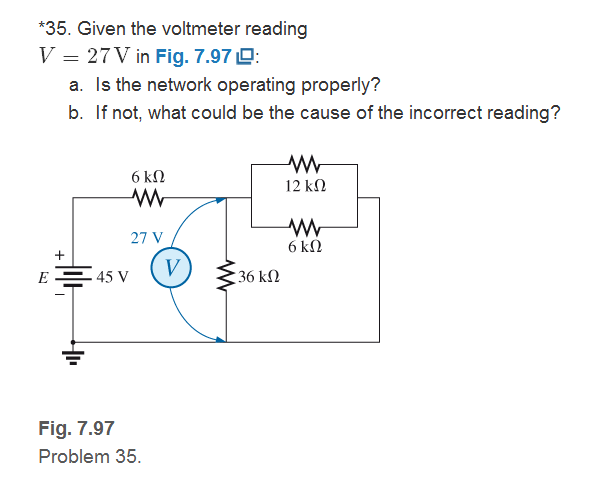
Fig. 7.97
Expert Solution & Answer
Want to see the full answer?
Check out a sample textbook solution
Students have asked these similar questions
Can you please provide an explanation and working. The solution is provided.
please show working and an explanation. The ans is 20.68 ms.
A 400V,50Hz,Y-connected, 4-pole,three-phase wound rotor induction motor, the rotor circuit is Y-
connected with R2=0.1, X2= 0.8 Q/ph .The measured e.m.f between two slip rings at 1440 rpm is
165 V. If the total stator losses are 650 W,find:airgap power, rotor copper loss, input power, developed
(or gross) mechanical power, output power, efficiency, if friction and windage losses are 377W?
Chapter 7 Solutions
Introductory Circuit Analysis (13th Edition)
Ch. 7 - Which elements (individual elements, not...Ch. 7 - Repeat Problem 1 for the networks of Fig. 7.65....Ch. 7 - Determine RT for the networks in Fig. 7.66. Fig....Ch. 7 - Determine RT for the networks in Fig. 7.67. Fig....Ch. 7 - Find the total resistance for the configuration of...Ch. 7 - The total resistance RT for the network of Fig....Ch. 7 - For the network in Fig. 7.70. a. Does...Ch. 7 - For the network in Fig. 7.71: a. Determine RT. b....Ch. 7 - For the network of Fig. 7.72: a. find the currents...Ch. 7 - For the network of Fig. 7.73: Find the voltages V3...
Ch. 7 - For the network of Fig. 7.74 a. Find the voltages...Ch. 7 - For the circuit board in Fig. 7.75: Find the total...Ch. 7 - Find the value of each resistor for the network of...Ch. 7 - Find the resistance RT for the network of Fig....Ch. 7 - For the network in Fig. 7.78: a. Find currents...Ch. 7 - a. Find the magnitude and direction of the...Ch. 7 - Determine the currents I1andI2 for the network in...Ch. 7 - For the network in Fig. 7.81: a. Determine the...Ch. 7 - For the network in Fig. 7.82: a. Determine the...Ch. 7 - Determine the dc levels for the transistor network...Ch. 7 - For the network in Fig. 7.84: Determine the...Ch. 7 - For the network in Fig. 7.852 Determine RT by...Ch. 7 - For the network of Fig. 7.86: a. Find the voltages...Ch. 7 - For the network in Fig. 7.87: a. Determine the...Ch. 7 - For the network in Fig. 7.88 find the resistance...Ch. 7 - If all the resistors of the cube in Fig. 7.89 are...Ch. 7 - For the ladder network in Fig. 7.90: a. Find the...Ch. 7 - For the ladder network in Fig. 7.91: a. Determine...Ch. 7 - Given the voltage divider supply in Fig. 7.92: a....Ch. 7 - Determine the voltage divider supply resistors for...Ch. 7 - A studio lamp requires 40 V at 50 mA to burn...Ch. 7 - For the system in Fig. 7.94 a. At first exposure,...Ch. 7 - For the potentiometer in Fig. 7.95: a. What are...Ch. 7 - Prob. 34PCh. 7 - Given the voltmeter reading V = 27 V in Fig. 7.97...Ch. 7 - Determine the power delivered to the 6 load in...Ch. 7 - For the multiple ladder configuration in Fig....Ch. 7 - An iron-vane movement is rated 1 mA, 100 . a. What...Ch. 7 - Using a 50 A, 1000 movement, design a multirange...Ch. 7 - An iron-vane movement is rated 50 A , 1000 a....Ch. 7 - Using a 1 mA, 1000 movement, design a multirange...Ch. 7 - A digital meter has an internal resistance of 10 M...Ch. 7 - a. Design a series ohmmeter using a 100 A, 1000...Ch. 7 - Prob. 44PCh. 7 - Determine the reading of the ohmmeter for each...Ch. 7 - Using PSpice or Multisim, verify the result of...Ch. 7 - Using PSpice or Multisim, Confirm the solutions of...Ch. 7 - Using PSpice or Multisim, verify the result of...Ch. 7 - Using PSpice or Multisim, find voltage V6 of Fig....Ch. 7 - Using PSpice or Multisim, find voltages Vb and Vc...
Knowledge Booster


Learn more about
Need a deep-dive on the concept behind this application? Look no further. Learn more about this topic, electrical-engineering and related others by exploring similar questions and additional content below.Similar questions
- consider the circuit below. Assume it uses ideal diodes with the details specified above. the left side of the circuit is basically a wheatstone bridge, hooked to the right side, which is a differential op amp. a) what is the voltage between junctions "A" and "B" if R2 is 201 ohms? b) what are the minimum and maximum values of R2 can be without the op amp hitting saturation?remember that for the diodes to be ideal you they have to have a turn on voltage of 0.6 volts.arrow_forwardThe capacitors in the circuit shown below have no energy stored in them and then switch “S1” closes at time t=0. Assume the ideal op amp does not saturate. As stated above assume the diodes are ideal with parameters specified above. Diodes are at 0.6 Volts Show the derivations of the mathematical equations for v(t) at Locations A and B for t≥ 0arrow_forwardPhase (deg) Magnitude (dB) -20 -40 -60 -80 -100 ° -90 -180 -270 10-1 (i) ° Problem 5 Consider a unity (negative) feedback system with a proportional controller. The Bode plot of the plant transfer function G(s) is given as below. System: sys Frequency (rad/s): 1 Magnitude (dB): 13.9 System: sys Frequency (rad/s): 14.9 Magnitude (dB): 6.58 System: sys Frequency (rad/s): 1 Phase (deg): -9.76 10° System: sys Frequency (rad/s): 25.6 Magnitude (dB): -0.0703 System: sys Frequency (rad/s): 41.3 Magnitude (dB): -8.06 System: sys Frequency (rad/s): 200 Magnitude (dB): -44.4 System: sys Frequency (rad/s): 14.9 Phase (deg): -110 System: sys Frequency (rad/s): 25.6 Phase (deg): -148 System: sys Frequency (rad/s): 41.3 Phase (deg): -180 System: sys Frequency (rad/s): 200 Phase (deg): -247 101 Frequency (rad/s) 102 Find the gain crossover frequency, phase crossover frequency, gain margin and phase margin of the system. Is the closed-loop system stable? (ii) What is the steady-state error of the…arrow_forward
- Problem 1 Consider the following system. In the figure, y(t) denotes the voltage across the capacitor. u(t) 1+ R W L + 0000 y(t) C Y(s) (i) Find the transfer function H(s): = of the system. U(s) Now suppose, R 10 KQ, L = 0.5 mH and C = 10 μF. (ii) Find the poles and zeros. Is the system BIBO stable? (iii) Compute settling time, rise time, peak time and % overshoot of the step response of the system. What the steady-state output for unit step input?arrow_forwardA 3-phase, 52 H.P, 50 Hz, 6-Pole, Y- connected induction motor runs at a speed of 980 rpm.The motor is supplied from 380 V mains and it takes a rated current of 80 A at 0.8 p.f. If the total stator losses are 1.7 kW, determine: the air-gap power, rotor copper loss, friction and windage losses?arrow_forwardelectric plants do hand writingarrow_forward
- please solve quickly. thank you!arrow_forwardPlease show all stepsarrow_forward12-3) PDF, mean, & variance A random variable has the PDF shown in the figure. a) Find the numerical value of the parameter K. b) Write the numerical expression for the PDF. c) Find the probability that the random variable is negative. d) Find the mean of x, the expected value of x², and the variance of x. K Px(x) 3 Xarrow_forward
arrow_back_ios
SEE MORE QUESTIONS
arrow_forward_ios
Recommended textbooks for you
 Delmar's Standard Textbook Of ElectricityElectrical EngineeringISBN:9781337900348Author:Stephen L. HermanPublisher:Cengage Learning
Delmar's Standard Textbook Of Electricity
Electrical Engineering
ISBN:9781337900348
Author:Stephen L. Herman
Publisher:Cengage Learning
Current Divider Rule; Author: Neso Academy;https://www.youtube.com/watch?v=hRU1mKWUehY;License: Standard YouTube License, CC-BY