
Concept explainers
Videos
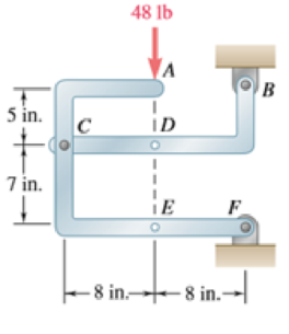
The 48-lb load is removed and a 288-lb · in. clockwise couple is applied successively at A, D, and E. Determine the components of the reactions at Band F if the couple is applied (a) at A, (b) at D, (c) at E.
(a)
The component of reactions at point B and F when the couple is applied at A.
Answer to Problem 6.89P
The x component of the reaction force at point B is
The x component of force applied is
Explanation of Solution
The free body diagram of the problem 6.89P is shown in figure 1 below.
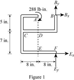
A clockwise couple is applied at A,D, and E. Due to this couple, resultant reaction forces are experienced in points A, D, and E.
First consider the couple applied at point A.
Write the equation to find the sum of moments of force at point F.
Here,
Since the sum of moments of force at a point of a system in equilibrium is zero, rewrite the equation for the sum of moments.
Write the equation to find the x components of force.
Here,
Since the sum of forces at a point is zero in equilibrium, the above equation is rewritten.
Substitute
Write the equation to find the sum of y component of forces.
Here,
No force is applied in the y direction, therefore there will be no reaction also.
Consider figure 2.
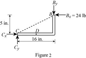
Write the equation to find the y component of reaction force at point B.
Here,
Rewrite equation (I) to find the value of
Conclusion:
Observe figure 2.
Substitute
The y component of reaction force at point B is having a magnitude of
Substitute
The y component of the force applied at point b is
Therefore, the x component of the reaction force at point B is
The x component of force applied is
(b)
The component of reactions at point B and F when the couple is applied at D.
Answer to Problem 6.89P
The x component of the reaction force at point B is
The x component of force applied is
Explanation of Solution
The free body diagram of the problem 6.89P is shown in figure 1.
A clockwise couple is applied at A,D, and E. Due to this couple, resultant reaction forces are experienced in points A, D, and E.
Consider the couple applied at point D.
Write the equation to find the sum of moments of force at point F.
Here,
Since the sum of moments of force at a point of a system in equilibrium is zero, rewrite the equation for the sum of moments.
Write the equation to find the x components of force.
Here,
Since the sum of forces at a point is zero in equilibrium, the above equation is rewritten.
Substitute
Write the equation to find the sum of y component of forces.
Here,
No force is applied in the y direction, therefore there will be no reaction also.
Consider figure 3.
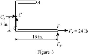
Write the equation to find the y component of reaction force at point B.
Here,
Rewrite equation (I) to find the value of
Conclusion:
Observe figure 3.
Substitute
The y component of force at point B is having a magnitude of
Substitute
The y component of the reaction force applied at point B is
Therefore, the x component of the reaction force at point B is
The x component of force applied is
(c)
The component of reactions at point B and F when the couple is applied at E.
Answer to Problem 6.89P
The x component of the reaction force at point B is
The x component of force applied is
Explanation of Solution
The free body diagram of the problem 6.89P is shown in figure 1.
A clockwise couple is applied at A,D, and E. Due to this couple, resultant reaction forces are experienced in points A, D, and E.
First consider the couple applied at point E.
Write the equation to find the sum of moments of force at point F.
Here,
Since the sum of moments of force at a point of a system in equilibrium is zero, rewrite the equation for the sum of moments.
Write the equation to find the x components of force.
Here,
Since the sum of forces at a point is zero in equilibrium, the above equation is rewritten.
Substitute
Write the equation to find the sum of y component of forces.
Here,
No force is applied in the y direction, therefore there will be no reaction also.
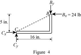
Consider figure 4.
Write the equation to find the y component of reaction force at point B.
Here,
Rewrite equation (VII) to find the value of
Conclusion:
Observe figure 4.
Substitute
The y component of reaction force at point B is having a magnitude of
Substitute
The y component of the force applied at point b is
Therefore, the x component of the reaction force at point B is
The x component of force applied is
Want to see more full solutions like this?
Chapter 6 Solutions
EBK VECTOR MECHANICS FOR ENGINEERS: STA


- 6. Consider a 10N step input to the mechanical system shown below, take M = 15kg, K = 135N/m, and b = 0.4 Ns/m. (a) Assume zero initial condition, calculate the (i) System pole (ii) System characterization, and (iii) The time domain response (b) Calculate the steady-state value of the system b [ www K 个 х M -F(+)arrow_forward2. Solve the following linear time invariant differential equations using Laplace transforms subject to different initial conditions (a) y-y=t for y(0) = 1 and y(0) = 1 (b) ÿ+4y+ 4y = u(t) for y(0) = 0 and y(0) = 1 (c) y-y-2y=0 for y(0) = 1 and y(0) = 0arrow_forward3. For the mechanical systems shown below, the springs are undeflected when x₁ = x2 = x3 = 0 and the input is given as fa(t). Draw the free-body diagrams and write the modeling equations governing each of the systems. K₁ 000 K₂ 000 M₁ M2 -fa(t) B₂ B₁ (a) fa(t) M2 K₂ 000 B K₁ x1 000 M₁ (b)arrow_forward
- This question i m uploading second time . before you provide me incorrect answer. read the question carefully and solve accordily.arrow_forward1. Create a table comparing five different analogous variables for translational, rotational, electrical and fluid systems. Include the standard symbols for each variable in their respective systems.arrow_forward2) Suppose that two unequal masses m₁ and m₂ are moving with initial velocities v₁ and v₂, respectively. The masses hit each other and have a coefficient of restitution e. After the impact, mass 1 and 2 head to their respective gaps at angles a and ẞ, respectively. Derive expressions for each of the angles in terms of the initial velocities and the coefficient of restitution. m1 m2 8 m1 m2 βarrow_forward
- 4. Find the equivalent spring constant and equivalent viscous-friction coefficient for the systems shown below. @ B₁ B₂ H B3 (b)arrow_forward5. The cart shown below is inclined 30 degrees with respect to the horizontal. At t=0s, the cart is released from rest (i.e. with no initial velocity). If the air resistance is proportional to the velocity squared. Analytically determine the initial acceleration and final or steady-state velocity of the cart. Take M= 900 kg and b 44.145 Ns²/m². Mg -bx 2 отarrow_forward9₁ A Insulated boundary Insulated boundary dx Let's begin with the strong form for a steady-state one-dimensional heat conduction problem, without convection. d dT + Q = dx dx According to Fourier's law of heat conduction, the heat flux q(x), is dT q(x)=-k dx. x Q is the internal heat source, which heat is generated per unit time per unit volume. q(x) and q(x + dx) are the heat flux conducted into the control volume at x and x + dx, respectively. k is thermal conductivity along the x direction, A is the cross-section area perpendicular to heat flux q(x). T is the temperature, and is the temperature gradient. dT dx 1. Derive the weak form using w(x) as the weight function. 2. Consider the following scenario: a 1D block is 3 m long (L = 3 m), with constant cross-section area A = 1 m². The left free surface of the block (x = 0) is maintained at a constant temperature of 200 °C, and the right surface (x = L = 3m) is insulated. Recall that Neumann boundary conditions are naturally satisfied…arrow_forward
- 1 - Clearly identify the system and its mass and energy exchanges between each system and its surroundings by drawing a box to represent the system boundary, and showing the exchanges by input and output arrows. You may want to search and check the systems on the Internet in case you are not familiar with their operations. A pot with boiling water on a gas stove A domestic electric water heater A motor cycle driven on the roadfrom thermodynamics You just need to draw and put arrows on the first part a b and carrow_forward7. A distributed load w(x) = 4x1/3 acts on the beam AB shown in Figure 7, where x is measured in meters and w is in kN/m. The length of the beam is L = 4 m. Find the moment of the resultant force about the point B. w(x) per unit length L Figure 7 Barrow_forward4. The press in Figure 4 is used to crush a small rock at E. The press comprises three links ABC, CDE and BG, pinned to each other at B and C, and to the ground at D and G. Sketch free-body diagrams of each component and hence determine the force exerted on the rock when a vertical force F = 400 N is applied at A. 210 80 80 C F 200 B 80 E 60% -O-D G All dimensions in mm. Figure 4arrow_forward
 International Edition---engineering Mechanics: St...Mechanical EngineeringISBN:9781305501607Author:Andrew Pytel And Jaan KiusalaasPublisher:CENGAGE L