
Concept explainers
Videos
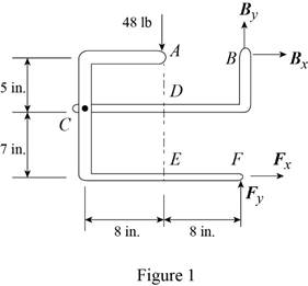
The 48-lb load can be moved along the line of action shown and applied at A, D, or E. Determine the components of the reactions at B and F if the 48-lb load is applied (a) at A, (b) at D, (c) at E.
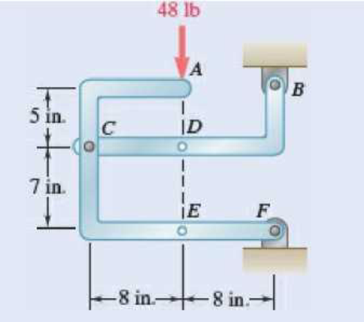
Fig. P6.88 and P6.89
SOLUTION
Free body: Entire frame:
The following analysis is valid for (a), (b) and (c) since the position of the load along its line of action is immaterial.
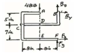
 ∑MF = 0: (48 lb)(8 in.) − Bx (12 in.) = 0
Bx = 32 lb Bx = 32 lb →
 ∑Fx = 0: 32 lb + Fx = 0
Fx = −32 lb Fx = 32 lb ←
+↑ ∑Fy = 0: By + Fy − 48 lb = 0 (1)
a) Load applied at A.
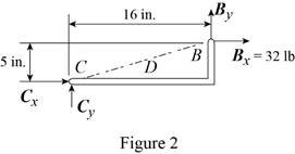
Free body: Member CDB
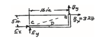
CDB is a two-force member. Thus, the reaction at B must be directed along BC.
From Eq. (1): 10 lb + Fy − 48 lb = 0
Fy = 38 lb Fy = 38 lb ↑
Thus reactions are:
Bx = 32.0 lb →, By = 10.00 lb ↑
Fx = 32.0 lb ←, Fy = 38.00 lb ↑
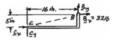
(b) Load applied at D.
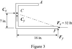
Free body: Member ACF.
ACF is a two-force member. Thus, the reaction at F must be directed along CF.
From Eq. (1): By + 14 lb – 48 lb = 0
By = 34 lb, By = 34 lb ↑
Thus, reactions are:
Bx = 32.0 lb ←, By = 34.00 lb ↑
Fx = 32.0 lb →, Fy = 14.00 lb ↑
(c) Load applied at E.
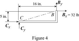
Free body: Member CDB.
This is the same free body as in Part (a).
Reactions are same as (a)
(a)
The components of reaction at
Answer to Problem 6.88P
The components of reaction at
Explanation of Solution
The arrangement is shown in Fig. P6.88. The free-body diagram of the entire frame is given in Figure 1.
Write the expressions for equilibrium for the given system using the conditions on moments
The counter clockwise moments at
The sum of
The sum of
The load is applied at
Conclusion:
Apply the condition in equation (I) to the free-body diagram in Figure 1 and solve for
Apply the condition in equation (II) to the free-body diagram in Figure 1 and solve for
Apply the condition in equation (III) to the free-body diagram in Figure 1.
From the free-body diagram in Figure 2, write the expression connecting the components of the reaction
Substitute
Substitute
Therefore, the components of reaction at
(b)
The components of reaction at
Answer to Problem 6.88P
The components of reaction at
Explanation of Solution
The
The load is applied at
Conclusion:
From the free-body diagram in Figure 3, write the expression connecting the components of the reaction
Substitute
Substitute
Therefore, the components of reaction at
(c)
The components of reaction at
Answer to Problem 6.88P
The components of reaction at
Explanation of Solution
The
The load is applied at
Conclusion:
The free-body diagram of the member
Therefore, the components of reaction at
Want to see more full solutions like this?
Chapter 6 Solutions
EBK VECTOR MECHANICS FOR ENGINEERS: STA


- The coefficient of friction between the part and the tool in cold working tends to be: lower higher no different relative to its value in hot workingarrow_forwardThe force F={25i−45j+15k}F={25i−45j+15k} lblb acts at the end A of the pipe assembly shown in (Figure 1). Determine the magnitude of the component F1 which acts along the member AB. Determine the magnitude of the component F2 which acts perpendicular to the AB.arrow_forwardHi can you please help me with the attached question?arrow_forward
- Please can you help me with the attached question?arrow_forwardPlease can you help me with the attached question?arrow_forward4. The rod ABCD is made of an aluminum for which E = 70 GPa. For the loading shown, determine the deflection of (a) point B, (b) point D. 1.75 m Area = 800 mm² 100 kN B 1.25 m с Area = 500 mm² 75 kN 1.5 m D 50 kNarrow_forward
 International Edition---engineering Mechanics: St...Mechanical EngineeringISBN:9781305501607Author:Andrew Pytel And Jaan KiusalaasPublisher:CENGAGE L