
Videos
6.119 through 6.121 Each of the frames shown consists of two L-shaped members connected by two rigid links. For each frame, determine the reactions at the supports and indicate whether the frame is rigid.
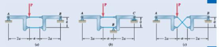
Fig. P6.120
The reactions at the frame and the rigidness of the frame.
Answer to Problem 6.120P
The reactions at the frame for figure (a) is
Explanation of Solution
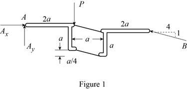
The following figure gives the free body diagram of the member in figure P6.120(a).
Write the equation to find the moment of force.
Here,
Write the equation to find the total moment about the point
Write the equations for equilibrium for the free body diagram in figure 1.
Here,
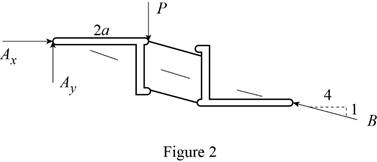
The following figure gives the free body diagram of the member in figure P6.120(b).
Write the equations for equilibrium for the free body diagram in figure 2.
Here,
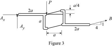
The following figure gives the free body diagram of the member in figure P6.120(c).
Write the equations for equilibrium for the free body diagram in figure 3.
Here,
Write the expression to find the magnitude of the vector from its components.
Here,
Write the equation to find the angle of orientation of the vector
Conclusion:
Solve equation (I) using figure 1.
Rewrite the above equation to find
Solve equation (II) using figure 1.
Substitute
Solve equation (III) using figure 1.
Substitute
Rewrite equation (VIII) in terms of the vector
Substitute
Rewrite equation (IX) in terms of the vector
Substitute
Solve equation (IV) using figure 2.
Solve equation (V) using figure 3.
Rewrite the above equation to find
Solve equation (VI) using figure 3.
Substitute
Solve equation (VII) using figure 3.
Substitute
Rewrite equation (VIII) in terms of the vector
Substitute
Rewrite equation (IX) in terms of the vector
Substitute
Therefore, the reactions at the frame for figure (a) is
Want to see more full solutions like this?
Chapter 6 Solutions
EBK VECTOR MECHANICS FOR ENGINEERS: STA


- The coefficient of friction between the part and the tool in cold working tends to be: lower higher no different relative to its value in hot workingarrow_forwardThe force F={25i−45j+15k}F={25i−45j+15k} lblb acts at the end A of the pipe assembly shown in (Figure 1). Determine the magnitude of the component F1 which acts along the member AB. Determine the magnitude of the component F2 which acts perpendicular to the AB.arrow_forwardHi can you please help me with the attached question?arrow_forward
- Please can you help me with the attached question?arrow_forwardPlease can you help me with the attached question?arrow_forward4. The rod ABCD is made of an aluminum for which E = 70 GPa. For the loading shown, determine the deflection of (a) point B, (b) point D. 1.75 m Area = 800 mm² 100 kN B 1.25 m с Area = 500 mm² 75 kN 1.5 m D 50 kNarrow_forward
 Elements Of ElectromagneticsMechanical EngineeringISBN:9780190698614Author:Sadiku, Matthew N. O.Publisher:Oxford University Press
 Mechanics of Materials (10th Edition)Mechanical EngineeringISBN:9780134319650Author:Russell C. HibbelerPublisher:PEARSON
 Thermodynamics: An Engineering ApproachMechanical EngineeringISBN:9781259822674Author:Yunus A. Cengel Dr., Michael A. BolesPublisher:McGraw-Hill Education
 Control Systems EngineeringMechanical EngineeringISBN:9781118170519Author:Norman S. NisePublisher:WILEY
 Mechanics of Materials (MindTap Course List)Mechanical EngineeringISBN:9781337093347Author:Barry J. Goodno, James M. GerePublisher:Cengage Learning
 Engineering Mechanics: StaticsMechanical EngineeringISBN:9781118807330Author:James L. Meriam, L. G. Kraige, J. N. BoltonPublisher:WILEY