
Videos
6.119 through 6.121 Each of the frames shown consists of two L-shaped members connected by two rigid links. For each frame, determine the reactions at the supports and indicate whether the frame is rigid.
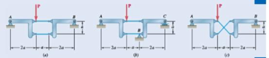
Fig. P6.121
The reactions at the frame and the rigidness of the frame.
Answer to Problem 6.121P
The reactions at the frame for figure (a) is
Explanation of Solution
The following figure gives the free body diagram of the first part of the member in figure P6.121(a).
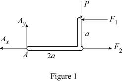
Write the equation to find the moment of force.
Here,
Write the equation to find the total moment about the point
Write the equations for equilibrium for the free body diagram in figure 1.
Here,
The following figure gives the free body diagram of the second part of the member in figure P6.121(a).
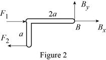
Write the equations for equilibrium for the free body diagram in figure 2.
Here,
The following figure gives the free body diagram of the first part of the member in figure P6.119(b).
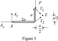
Write the equations for equilibrium for the free body diagram in figure 3.
Here,
The following figure gives the free body diagram of the second part of the member in figure P6.119(b).
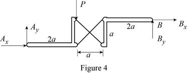
Write the equations for equilibrium for the free body diagram in figure 4.
Here,
The following figure gives the free body diagram of the member in figure P6.119(c).
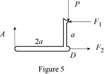
Write the equations for equilibrium for the free body diagram in figure 5.
Here,
The following figure gives the free body diagram of right part of the member in figure P6.119(c).
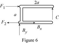
Write the equations for equilibrium for the free body diagram in figure 6.
Here,
Write the expression to find the magnitude of the vector from its components.
Here,
Write the equation to find the angle of orientation of the vector
Conclusion:
Solve equation (I) using figure 1.
Rewrite the above equation.
Solve equation (III) using figure 1.
Rewrite the above equation.
Solve equation (IV) using figure 2.
Rewrite the above equation.
Solve equation (V) using figure 2.
Substitute
Solve equation (VI) using figure 2.
Substitute
Rewrite equation (XIV) in terms of the vector
Substitute
Rewrite equation (XV) in terms of the vector
Substitute
Rewrite equation (XIV) in terms of the vector
Substitute
Solve equation (VII) using figure 3.
Rewrite the above equation.
Solve equation (VIII) using figure 4.
Rewrite the above equation.
Solve the conditions obtained from figure 3 and 4.
Solve equation (IX) using figure 5.
Rewrite the above equation to find
Solve equation (X) using figure 5.
Substitute
Solve equation (XI) using figure 5.
Substitute
Solve equation (XII) using figure 6.
Substitute
Solve equation (XII) to the right using figure 6.
Substitute
Solve equation (XII) upwards using figure 6.
Substitute
Therefore, the reactions at the frame for figure (a) is
Want to see more full solutions like this?
Chapter 6 Solutions
VECTOR MECH...,STAT.+DYNA.(LL)-W/ACCESS


- Determine the moments of the force about the x and the a axes. O 4 m F = {-40i +20j + 10k} N 3 m 6 m aarrow_forward6. A part of the structure for a factory automation system is a beam that spans 30.0 in as shown in Figure P5-6. Loads are applied at two points, each 8.0 in from a support. The left load F₁ = 1800 lb remains constantly applied, while the right load F₂ = 1800 lb is applied and removed fre- quently as the machine cycles. Evaluate the beam at both B and C. A 8 in F₁ = 1800 lb 14 in F2 = 1800 lb 8 in D RA B C 4X2X1/4 Steel tube Beam cross section RDarrow_forward30. Repeat Problem 28, except using a shaft that is rotating and transmitting a torque of 150 N⚫m from the left bear- ing to the middle of the shaft. Also, there is a profile key- seat at the middle under the load.arrow_forward
- 28. The shaft shown in Figure P5-28 is supported by bear- ings at each end, which have bores of 20.0 mm. Design the shaft to carry the given load if it is steady and the shaft is stationary. Make the dimension a as large as pos- sible while keeping the stress safe. Determine the required d = 20mm D = ? R = ?| 5.4 kN d=20mm Length not to scale -a = ?- +а= a = ? + -125 mm- -250 mm- FIGURE P5-28 (Problems 28, 29, and 30)arrow_forward12. Compute the estimated actual endurance limit for SAE 4130 WQT 1300 steel bar with a rectangular cross sec- tion of 20.0 mm by 60 mm. It is to be machined and subjected to repeated and reversed bending stress. A reli- ability of 99% is desired.arrow_forward28. The shaft shown in Figure P5-28 is supported by bear- ings at each end, which have bores of 20.0 mm. Design the shaft to carry the given load if it is steady and the shaft is stationary. Make the dimension a as large as pos- sible while keeping the stress safe. Determine the required d = 20mm D = ? R = ?| 5.4 kN d=20mm Length not to scale -a = ?- +а= a = ? + -125 mm- -250 mm- FIGURE P5-28 (Problems 28, 29, and 30)arrow_forward
- 2. A strut in a space frame has a rectangular cross section of 10.0 mm by 30.0 mm. It sees a load that varies from a tensile force of 20.0 kN to a compressive force of 8.0 kN.arrow_forwardfind stress at Qarrow_forwardI had a theoretical question about attitude determination. In the attached images, I gave two axis and angles. The coefficient of the axes are the same and the angles are the same. The only difference is the vector basis. Lets say there is a rotation going from n hat to b hat. Then, you introduce a intermediate rotation s hat. So, I want to know if the DCM produced from both axis and angles will be the same or not. Does the vector basis affect the numerical value of the DCM? The DCM formula only cares about the coefficient of the axis and the angle. So, they should be the same right?arrow_forward
- 3-15. A small fixed tube is shaped in the form of a vertical helix of radius a and helix angle y, that is, the tube always makes an angle y with the horizontal. A particle of mass m slides down the tube under the action of gravity. If there is a coefficient of friction μ between the tube and the particle, what is the steady-state speed of the particle? Let y γ 30° and assume that µ < 1/√3.arrow_forwardThe plate is moving at 0.6 mm/s when the force applied to the plate is 4mN. If the surface area of the plate in contact with the liquid is 0.5 m^2, deterimine the approximate viscosity of the liquid, assuming that the velocity distribution is linear.arrow_forward3-9. Given that the force acting on a particle has the following components: Fx = −x + y, Fy = x − y + y², F₂ = 0. Solve for the potential energy V. -arrow_forward
 Elements Of ElectromagneticsMechanical EngineeringISBN:9780190698614Author:Sadiku, Matthew N. O.Publisher:Oxford University Press
 Mechanics of Materials (10th Edition)Mechanical EngineeringISBN:9780134319650Author:Russell C. HibbelerPublisher:PEARSON
 Thermodynamics: An Engineering ApproachMechanical EngineeringISBN:9781259822674Author:Yunus A. Cengel Dr., Michael A. BolesPublisher:McGraw-Hill Education
 Control Systems EngineeringMechanical EngineeringISBN:9781118170519Author:Norman S. NisePublisher:WILEY
 Mechanics of Materials (MindTap Course List)Mechanical EngineeringISBN:9781337093347Author:Barry J. Goodno, James M. GerePublisher:Cengage Learning
 Engineering Mechanics: StaticsMechanical EngineeringISBN:9781118807330Author:James L. Meriam, L. G. Kraige, J. N. BoltonPublisher:WILEY