
VECTOR MECH...,STAT.+DYNA.(LL)-W/ACCESS
11th Edition
ISBN: 9781259633133
Author: BEER
Publisher: MCG
expand_more
expand_more
format_list_bulleted
Concept explainers
Videos
Textbook Question
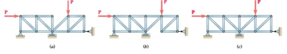
Chapter 6.2, Problem 6.69P
Classify each of the structures shown as completely, partially, or improperly constrained; if completely constrained, further classify as determinate or indeterminate. (All members can act both in tension and in compression.)
Expert Solution & Answer
Want to see the full answer?
Check out a sample textbook solution
Students have asked these similar questions
2. Find a basis of solutions by the Frobenius method. Try to identify the series as expansions of
known functions.
(x + 2)²y" + (x + 2)y' - y = 0 ; Hint: Let: z = x+2
1. Find a power series solution in powers of x.
y" - y' + x²y = 0
3. Find a basis of solutions by the Frobenius method. Try to identify the series as expansions of
known functions.
8x2y" +10xy' + (x 1)y = 0
-
Chapter 6 Solutions
VECTOR MECH...,STAT.+DYNA.(LL)-W/ACCESS
Ch. 6.1 - 6.1 through 6.8 Using the method of joints,...Ch. 6.1 - 6.1 through 6.8 Using the method of joints,...Ch. 6.1 - Prob. 6.3PCh. 6.1 - 6.1 through 6.8 Using the method of joints,...Ch. 6.1 - Prob. 6.5PCh. 6.1 - Using the method of joints, determine the force in...Ch. 6.1 - 6.1 through 6.8 Using the method of joints,...Ch. 6.1 - Prob. 6.8PCh. 6.1 - 6.9 and 6.10 Determine the force in each member of...Ch. 6.1 - Prob. 6.10P
Ch. 6.1 - Determine the force in each member of the Gambrel...Ch. 6.1 - Determine the force in each member of the Howe...Ch. 6.1 - Using the method of joints, determine the force in...Ch. 6.1 - 6.14 Determine the force in each member of the...Ch. 6.1 - Determine the force in each member of the Warren...Ch. 6.1 - Solve Problem 6.15 assuming that the load applied...Ch. 6.1 - Determine the force in each member of the Pratt...Ch. 6.1 - The truss shown is one of several supporting an...Ch. 6.1 - Determine the force in each member of the Pratt...Ch. 6.1 - Prob. 6.20PCh. 6.1 - Determine the force in each of the members located...Ch. 6.1 - Determine the force in member DE and in each of...Ch. 6.1 - Determine the force in each of the members located...Ch. 6.1 - The portion of truss shown represents the upper...Ch. 6.1 - For the tower and loading of Prob. 6.24 and...Ch. 6.1 - Solve Problem 6.24 assuming that the cables...Ch. 6.1 - Determine the force in each member of the truss...Ch. 6.1 - Determine the force in each member of the truss...Ch. 6.1 - 6.29 Determine whether the trusses of Probs....Ch. 6.1 - 6.30 Determine whether the trusses of Probs....Ch. 6.1 - Prob. 6.31PCh. 6.1 - Prob. 6.32PCh. 6.1 - For the given loading, determine the zero-force...Ch. 6.1 - Prob. 6.34PCh. 6.1 - Prob. 6.35PCh. 6.1 - Prob. 6.36PCh. 6.1 - The truss shown consists of six members and is...Ch. 6.1 - The truss shown consists of nine members and is...Ch. 6.1 - The truss shown consists of nine members and is...Ch. 6.1 - Solve Prob. 6.39 for P = 0 and Q = (900 N)k. 6.39...Ch. 6.1 - The truss shown consists of 18 members and is...Ch. 6.1 - The truss shown consists of 18 members and is...Ch. 6.2 - 6.43 A Mansard roof truss is loaded as shown....Ch. 6.2 - 6.44 A Mansard roof truss is loaded as shown....Ch. 6.2 - Determine the force in members BD and CD of the...Ch. 6.2 - Determine the force in members DF and DG of the...Ch. 6.2 - Prob. 6.47PCh. 6.2 - Prob. 6.48PCh. 6.2 - Determine the force in members CD and DF of the...Ch. 6.2 - Determine the force in members CE and EF of the...Ch. 6.2 - Determine the force in members DE and DF of the...Ch. 6.2 - Prob. 6.52PCh. 6.2 - Determine the force in members DF and DE of the...Ch. 6.2 - Prob. 6.54PCh. 6.2 - Prob. 6.55PCh. 6.2 - 6.56 A monosloped roof truss is loaded as shown....Ch. 6.2 - A Howe scissors roof truss is loaded as shown....Ch. 6.2 - A Howe scissors roof truss is loaded as shown....Ch. 6.2 - Determine the force in members AD, CD, and CE of...Ch. 6.2 - Determine the force in members DG, FG, and FH of...Ch. 6.2 - 6.61 Determine the force in members DG and FI of...Ch. 6.2 - Prob. 6.62PCh. 6.2 - Prob. 6.63PCh. 6.2 - Prob. 6.64PCh. 6.2 - The diagonal members in the center panels of the...Ch. 6.2 - The diagonal members in the center panels of the...Ch. 6.2 - Prob. 6.67PCh. 6.2 - Prob. 6.68PCh. 6.2 - Classify each of the structures shown as...Ch. 6.2 - Classify each of the structures shown as...Ch. 6.2 - Prob. 6.71PCh. 6.2 - 6.70 through 6.74 classify as determinate or...Ch. 6.2 - 6.70 through 6.74 classify as determinate or...Ch. 6.2 - 6.70 through 6.74 classify as determinate or...Ch. 6.3 - For the frame and loading shown, draw the...Ch. 6.3 - For the frame and loading shown, draw the...Ch. 6.3 - Draw the free-body diagram(s) needed to determine...Ch. 6.3 - Knowing that the pulley has a radius of 0.5 m,...Ch. 6.3 - 6.75 and 6.76 Determine the force in member BD and...Ch. 6.3 - 6.75 and 6.76 Determine the force in member BD and...Ch. 6.3 - For the frame and loading shown, determine the...Ch. 6.3 - Determine the components of all forces acting on...Ch. 6.3 - Prob. 6.79PCh. 6.3 - Prob. 6.80PCh. 6.3 - Determine the components of all forces acting on...Ch. 6.3 - Determine the components of all forces acting on...Ch. 6.3 - Determine the components of the reactions at A and...Ch. 6.3 - Determine the components of the reactions at D and...Ch. 6.3 - Determine the components of the reactions at A and...Ch. 6.3 - Determine the components of the reactions at A and...Ch. 6.3 - 6.87 Determine the components of the reactions at...Ch. 6.3 - The 48-lb load can be moved along the line of...Ch. 6.3 - The 48-lb load is removed and a 288-lb in....Ch. 6.3 - (a) Show that, when a frame supports a pulley at...Ch. 6.3 - Knowing that each pulley has a radius of 250 mm,...Ch. 6.3 - Knowing that the pulley has a radius of 75 mm,...Ch. 6.3 - Prob. 6.93PCh. 6.3 - Prob. 6.94PCh. 6.3 - Prob. 6.95PCh. 6.3 - Prob. 6.96PCh. 6.3 - Prob. 6.97PCh. 6.3 - Prob. 6.98PCh. 6.3 - Knowing that P = 90 lb and Q = 60 lb, determine...Ch. 6.3 - Knowing that P = 90 lb and Q = 60 lb, determine...Ch. 6.3 - For the frame and loading shown, determine the...Ch. 6.3 - For the frame and loading shown, determine the...Ch. 6.3 - Prob. 6.103PCh. 6.3 - 6.104 Solve Prob. 6.103 assuming that the 360-lb...Ch. 6.3 - For the frame and loading shown, determine the...Ch. 6.3 - Prob. 6.106PCh. 6.3 - The axis of the three-hinge arch ABC is a parabola...Ch. 6.3 - The axis of the three-hinge arch ABC is a parabola...Ch. 6.3 - Prob. 6.109PCh. 6.3 - Prob. 6.110PCh. 6.3 - 6.111, 6.112, and 6.113 Members ABC and CDE are...Ch. 6.3 - Prob. 6.112PCh. 6.3 - 6.111, 6.112, and 6.113 Members ABC and CDE are...Ch. 6.3 - Prob. 6.114PCh. 6.3 - Solve Prob. 6.112 assuming that the force P is...Ch. 6.3 - Prob. 6.116PCh. 6.3 - Prob. 6.117PCh. 6.3 - Prob. 6.118PCh. 6.3 - 6.119 through 6.121 Each of the frames shown...Ch. 6.3 - 6.119 through 6.121 Each of the frames shown...Ch. 6.3 - 6.119 through 6.121 Each of the frames shown...Ch. 6.4 - An 84-lb force is applied to the toggle vise at C....Ch. 6.4 - For the system and loading shown, draw the...Ch. 6.4 - Prob. 6.7FBPCh. 6.4 - The position of member ABC is controlled by the...Ch. 6.4 - The shear shown is used to cut and trim...Ch. 6.4 - A 100-lb force directed vertically downward is...Ch. 6.4 - Prob. 6.124PCh. 6.4 - The control rod CE passes through a horizontal...Ch. 6.4 - Solve Prob. 6.125 when (a) = 0, (b) = 6. Fig....Ch. 6.4 - The press shown is used to emboss a small seal at...Ch. 6.4 - The press shown is used to emboss a small seal at...Ch. 6.4 - Prob. 6.129PCh. 6.4 - The pin at B is attached to member ABC and can...Ch. 6.4 - Arm ABC is connected by pins to a collar at B and...Ch. 6.4 - Arm ABC is connected by pins to a collar at B and...Ch. 6.4 - The Whitworth mechanism shown is used to produce a...Ch. 6.4 - Prob. 6.134PCh. 6.4 - Prob. 6.135PCh. 6.4 - Prob. 6.136PCh. 6.4 - 6.137 and 6.138 Rod CD is attached to the collar D...Ch. 6.4 - 6.137 and 6.138 Rod CD is attached to the collar D...Ch. 6.4 - Two hydraulic cylinders control the position of...Ch. 6.4 - Prob. 6.140PCh. 6.4 - Prob. 6.141PCh. 6.4 - Prob. 6.142PCh. 6.4 - Prob. 6.143PCh. 6.4 - Prob. 6.144PCh. 6.4 - The pliers shown are used to grip a...Ch. 6.4 - 6.146 Determine the magnitude of the gripping...Ch. 6.4 - In using the bolt cutter shown, a worker applies...Ch. 6.4 - Prob. 6.148PCh. 6.4 - Prob. 6.149PCh. 6.4 - and 6.150 Determine the force P that must be...Ch. 6.4 - Prob. 6.151PCh. 6.4 - Prob. 6.152PCh. 6.4 - 6.153 The motion of the bucket of the front-end...Ch. 6.4 - Prob. 6.154PCh. 6.4 - The telescoping arm ABC is used to provide an...Ch. 6.4 - The telescoping arm ABC of Prob. 6.155 can be...Ch. 6.4 - The motion of the backhoe bucket shown is...Ch. 6.4 - Prob. 6.158PCh. 6.4 - Prob. 6.159PCh. 6.4 - In the planetary gear system shown, the radius of...Ch. 6.4 - Two shafts AC and CF, which lie in the vertical xy...Ch. 6.4 - Two shafts AC and CF, which lie in the vertical xy...Ch. 6.4 - The large mechanical tongs shown are used to grab...Ch. 6 - Using the method of joints, determine the force in...Ch. 6 - Using the method of joints, determine the force in...Ch. 6 - A stadium roof truss is loaded as shown. Determine...Ch. 6 - A stadium roof truss is loaded as shown. Determine...Ch. 6 - Determine the components of all forces acting on...Ch. 6 - Prob. 6.169RPCh. 6 - Knowing that the pulley has a radius of 50 mm,...Ch. 6 - For the frame and loading shown, determine the...Ch. 6 - For the frame and loading shown, determine the...Ch. 6 - Water pressure in the supply system exerts a...Ch. 6 - A couple M with a magnitude of 1.5 kNm is applied...Ch. 6 - Prob. 6.175RP
Additional Engineering Textbook Solutions
Find more solutions based on key concepts
How does a computers main memory differ from its auxiliary memory?
Java: An Introduction to Problem Solving and Programming (8th Edition)
The solid steel shaft AC has a diameter of 25 mm and is supported by smooth bearings at D and E. It is coupled ...
Mechanics of Materials (10th Edition)
Why is the study of database technology important?
Database Concepts (8th Edition)
Assume a telephone signal travels through a cable at two-thirds the speed of light. How long does it take the s...
Electric Circuits. (11th Edition)
17–1C A high-speed aircraft is cruising in still air. How does the temperature of air at the nose of the aircra...
Thermodynamics: An Engineering Approach
How are relationships between tables expressed in a relational database?
Modern Database Management
Knowledge Booster


Learn more about
Need a deep-dive on the concept behind this application? Look no further. Learn more about this topic, mechanical-engineering and related others by exploring similar questions and additional content below.Similar questions
- Hello I was going over the solution for this probem and I'm a bit confused on the last part. Can you please explain to me 1^4 was used for the Co of the tubular cross section? Thank you!arrow_forwardBlood (HD = 0.45 in large diameter tubes) is forced through hollow fiber tubes that are 20 µm in diameter.Equating the volumetric flowrate expressions from (1) assuming marginal zone theory and (2) using an apparentviscosity for the blood, estimate the marginal zone thickness at this diameter. The viscosity of plasma is 1.2 cParrow_forwardQ2: Find the shear load on bolt A for the connection shown in Figure 2. Dimensions are in mm Fig. 2 24 0-0 0-0 A 180kN (10 Markarrow_forward
- determine the direction and magnitude of angular velocity ω3 of link CD in the four-bar linkage using the relative velocity graphical methodarrow_forwardFour-bar linkage mechanism, AB=40mm, BC=60mm, CD=70mm, AD=80mm, =60°, w1=10rad/s. Determine the direction and magnitude of w3 using relative motion graphical method. A B 2 3 77777 477777arrow_forwardFour-bar linkage mechanism, AB=40mm, BC=60mm, CD=70mm, AD=80mm, =60°, w1=10rad/s. Determine the direction and magnitude of w3 using relative motion graphical method. A B 2 3 77777 477777arrow_forward
- The evaporator of a vapor compression refrigeration cycle utilizing R-123 as the refrigerant isbeing used to chill water. The evaporator is a shell and tube heat exchanger with the water flowingthrough the tubes. The water enters the heat exchanger at a temperature of 54°F. The approachtemperature difference of the evaporator is 3°R. The evaporating pressure of the refrigeration cycleis 4.8 psia and the condensing pressure is 75 psia. The refrigerant is flowing through the cycle witha flow rate of 18,000 lbm/hr. The R-123 leaves the evaporator as a saturated vapor and leaves thecondenser as a saturated liquid. Determine the following:a. The outlet temperature of the chilled waterb. The volumetric flow rate of the chilled water (gpm)c. The UA product of the evaporator (Btu/h-°F)d. The heat transfer rate between the refrigerant and the water (tons)arrow_forward(Read image) (Answer given)arrow_forwardProblem (17): water flowing in an open channel of a rectangular cross-section with width (b) transitions from a mild slope to a steep slope (i.e., from subcritical to supercritical flow) with normal water depths of (y₁) and (y2), respectively. Given the values of y₁ [m], y₂ [m], and b [m], calculate the discharge in the channel (Q) in [Lit/s]. Givens: y1 = 4.112 m y2 = 0.387 m b = 0.942 m Answers: ( 1 ) 1880.186 lit/s ( 2 ) 4042.945 lit/s ( 3 ) 2553.11 lit/s ( 4 ) 3130.448 lit/sarrow_forward
- Problem (14): A pump is being used to lift water from an underground tank through a pipe of diameter (d) at discharge (Q). The total head loss until the pump entrance can be calculated as (h₁ = K[V²/2g]), h where (V) is the flow velocity in the pipe. The elevation difference between the pump and tank surface is (h). Given the values of h [cm], d [cm], and K [-], calculate the maximum discharge Q [Lit/s] beyond which cavitation would take place at the pump entrance. Assume Turbulent flow conditions. Givens: h = 120.31 cm d = 14.455 cm K = 8.976 Q Answers: (1) 94.917 lit/s (2) 49.048 lit/s ( 3 ) 80.722 lit/s 68.588 lit/s 4arrow_forwardProblem (13): A pump is being used to lift water from the bottom tank to the top tank in a galvanized iron pipe at a discharge (Q). The length and diameter of the pipe section from the bottom tank to the pump are (L₁) and (d₁), respectively. The length and diameter of the pipe section from the pump to the top tank are (L2) and (d2), respectively. Given the values of Q [L/s], L₁ [m], d₁ [m], L₂ [m], d₂ [m], calculate total head loss due to friction (i.e., major loss) in the pipe (hmajor-loss) in [cm]. Givens: L₁,d₁ Pump L₂,d2 오 0.533 lit/s L1 = 6920.729 m d1 = 1.065 m L2 = 70.946 m d2 0.072 m Answers: (1) 3.069 cm (2) 3.914 cm ( 3 ) 2.519 cm ( 4 ) 1.855 cm TABLE 8.1 Equivalent Roughness for New Pipes Pipe Riveted steel Concrete Wood stave Cast iron Galvanized iron Equivalent Roughness, & Feet Millimeters 0.003-0.03 0.9-9.0 0.001-0.01 0.3-3.0 0.0006-0.003 0.18-0.9 0.00085 0.26 0.0005 0.15 0.045 0.000005 0.0015 0.0 (smooth) 0.0 (smooth) Commercial steel or wrought iron 0.00015 Drawn…arrow_forwardThe flow rate is 12.275 Liters/s and the diameter is 6.266 cm.arrow_forward
arrow_back_ios
SEE MORE QUESTIONS
arrow_forward_ios
Recommended textbooks for you
 Elements Of ElectromagneticsMechanical EngineeringISBN:9780190698614Author:Sadiku, Matthew N. O.Publisher:Oxford University Press
 Mechanics of Materials (10th Edition)Mechanical EngineeringISBN:9780134319650Author:Russell C. HibbelerPublisher:PEARSON
 Thermodynamics: An Engineering ApproachMechanical EngineeringISBN:9781259822674Author:Yunus A. Cengel Dr., Michael A. BolesPublisher:McGraw-Hill Education
 Control Systems EngineeringMechanical EngineeringISBN:9781118170519Author:Norman S. NisePublisher:WILEY
 Mechanics of Materials (MindTap Course List)Mechanical EngineeringISBN:9781337093347Author:Barry J. Goodno, James M. GerePublisher:Cengage Learning
 Engineering Mechanics: StaticsMechanical EngineeringISBN:9781118807330Author:James L. Meriam, L. G. Kraige, J. N. BoltonPublisher:WILEY
Elements Of Electromagnetics
Mechanical Engineering
ISBN:9780190698614
Author:Sadiku, Matthew N. O.
Publisher:Oxford University Press
Mechanics of Materials (10th Edition)
Mechanical Engineering
ISBN:9780134319650
Author:Russell C. Hibbeler
Publisher:PEARSON
Thermodynamics: An Engineering Approach
Mechanical Engineering
ISBN:9781259822674
Author:Yunus A. Cengel Dr., Michael A. Boles
Publisher:McGraw-Hill Education
Control Systems Engineering
Mechanical Engineering
ISBN:9781118170519
Author:Norman S. Nise
Publisher:WILEY
Mechanics of Materials (MindTap Course List)
Mechanical Engineering
ISBN:9781337093347
Author:Barry J. Goodno, James M. Gere
Publisher:Cengage Learning
Engineering Mechanics: Statics
Mechanical Engineering
ISBN:9781118807330
Author:James L. Meriam, L. G. Kraige, J. N. Bolton
Publisher:WILEY
EVERYTHING on Axial Loading Normal Stress in 10 MINUTES - Mechanics of Materials; Author: Less Boring Lectures;https://www.youtube.com/watch?v=jQ-fNqZWrNg;License: Standard YouTube License, CC-BY