
Concept explainers
Videos
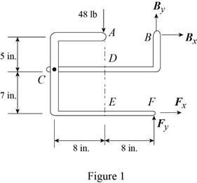
The 48-lb load can be moved along the line of action shown and applied at A, D, or E. Determine the components of the reactions at B and F if the 48-lb load is applied (a) at A, (b) at D, (c) at E.
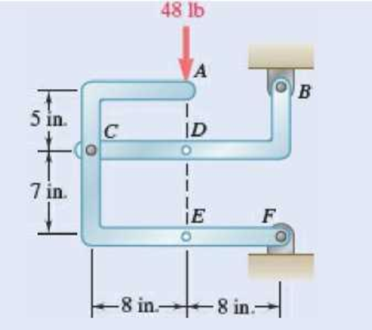
Fig. P6.88 and P6.89
SOLUTION
Free body: Entire frame:
The following analysis is valid for (a), (b) and (c) since the position of the load along its line of action is immaterial.
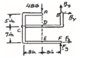
 ∑MF = 0: (48 lb)(8 in.) − Bx (12 in.) = 0
Bx = 32 lb Bx = 32 lb →
 ∑Fx = 0: 32 lb + Fx = 0
Fx = −32 lb Fx = 32 lb ←
+↑ ∑Fy = 0: By + Fy − 48 lb = 0 (1)
a) Load applied at A.
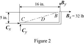
Free body: Member CDB
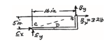
CDB is a two-force member. Thus, the reaction at B must be directed along BC.
From Eq. (1): 10 lb + Fy − 48 lb = 0
Fy = 38 lb Fy = 38 lb ↑
Thus reactions are:
Bx = 32.0 lb →, By = 10.00 lb ↑
Fx = 32.0 lb ←, Fy = 38.00 lb ↑
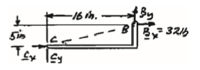
(b) Load applied at D.
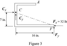
Free body: Member ACF.
ACF is a two-force member. Thus, the reaction at F must be directed along CF.
From Eq. (1): By + 14 lb – 48 lb = 0
By = 34 lb, By = 34 lb ↑
Thus, reactions are:
Bx = 32.0 lb ←, By = 34.00 lb ↑
Fx = 32.0 lb →, Fy = 14.00 lb ↑
(c) Load applied at E.
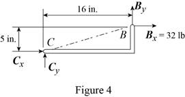
Free body: Member CDB.
This is the same free body as in Part (a).
Reactions are same as (a)
(a)
The components of reaction at
Answer to Problem 6.88P
The components of reaction at
Explanation of Solution
The arrangement is shown in Fig. P6.88. The free-body diagram of the entire frame is given in Figure 1.
Write the expressions for equilibrium for the given system using the conditions on moments
The counter clockwise moments at
The sum of
The sum of
The load is applied at
Conclusion:
Apply the condition in equation (I) to the free-body diagram in Figure 1 and solve for
Apply the condition in equation (II) to the free-body diagram in Figure 1 and solve for
Apply the condition in equation (III) to the free-body diagram in Figure 1.
From the free-body diagram in Figure 2, write the expression connecting the components of the reaction
Substitute
Substitute
Therefore, the components of reaction at
(b)
The components of reaction at
Answer to Problem 6.88P
The components of reaction at
Explanation of Solution
The
The load is applied at
Conclusion:
From the free-body diagram in Figure 3, write the expression connecting the components of the reaction
Substitute
Substitute
Therefore, the components of reaction at
(c)
The components of reaction at
Answer to Problem 6.88P
The components of reaction at
Explanation of Solution
The
The load is applied at
Conclusion:
The free-body diagram of the member
Therefore, the components of reaction at
Want to see more full solutions like this?
Chapter 6 Solutions
VECTOR MECH...,STAT.+DYNA.(LL)-W/ACCESS


- Sketch and explain a PV Diagram and a Temperature Entropy Diagram for a 4 stroke diesel engine please, please explain into detail the difference bewteen the two and referance the a diagram. Please include a sketch or an image of each diagramarrow_forwardDraw left view of the first orthographic projectionarrow_forwardSketch and Describe a timing diagram for a 2 stroke diesel engine emphasis on the 2 stroke as my last answer explained 4 stroke please include a diagram or sketch.arrow_forward
- A 4 ft 200 Ib 1000 Ib.ft C 2 ft 350 Ib - за в 2.5 ft 150 Ib 250 Ib 375 300 Ib Replace the force system acting on the frame. shown in the figure by a resultant force (magnitude and direction), and specify where its line of action intersects member (AB), measured from point (A).arrow_forwardA continuous flow calorimeter was used to obtain the calorific value of a sample of fuel and the following data collected: Mass of fuel: 2.25 kgInlet water temperature: 11 ° COutlet water temperature 60 ° CQuantity of water: 360 Liters Calorimeter efficiency: 85%Calculate the calorific value of the sample ( kJ / kg ). ive submitted this question twice and have gotten two way different answers. looking for some help thanksarrow_forward15 kg of steel ball bearings at 100 ° C is immersed in 25 kg of water at 20 ° C . Assuming no loss of heat to or from the container, calculate the final temperature of the water after equilibrium has been attained.Specific heat of steel: 0.4857 kJ / kg / ° KSpecific heat of water: 4.187 kJ / kg / ° Karrow_forward
- Sketch and explain a PV Diagram and a Temperature Entropy Diagram for a 4 stroke diesel enginearrow_forwardA continuous flow calorimeter was used to obtain the calorific value of a sample of fuel and the following data collected: Mass of fuel: 2.25 kgInlet water temperature: 11 ° COutlet water temperature 60 ° CQuantity of water: 360 Liters Calorimeter efficiency: 85%Calculate the calorific value of the sample ( kJ / kg ).arrow_forwardChapter 12 - Lecture Notes.pptx: (MAE 272-01) (SP25) DY... Scoresarrow_forwardmylabmastering.pearson.com Chapter 12 - Lecture Notes.pptx: (MAE 272-01) (SP25) DY... P Pearson MyLab and Mastering Scoresarrow_forwardanswer the fallowing Brake Specific Fuel Consumption - 0.3 kg/kwh, Mechanical Efficiency- 90% Calorific Value of Fuel -45 MJ/kg. Given these values, find the indicated power, indicated thermal efficiency and brake thermal efficiencyarrow_forwardProblem 6. The circular plate shown rotates about its vertical diameter. At the instant shown, the angular velocity ₁ of the plate is 10 rad/s and is decreasing at the rate of 25 rad/s². The disk lies in the XY plane and Point D of strap CD moves upward. The relative speed u of Point D of strap CD is 1.5 m/s and is decreasing at the rate of 3 m/s². Determine (a) the velocity of D, (b) the acceleration of D. Answers: =0.75 +1.299]-1.732k m/s a=-28.6 +3.03-10.67k m/s² 200 mm x Zarrow_forwardarrow_back_iosSEE MORE QUESTIONSarrow_forward_iosRecommended textbooks for you
 International Edition---engineering Mechanics: St...Mechanical EngineeringISBN:9781305501607Author:Andrew Pytel And Jaan KiusalaasPublisher:CENGAGE L
International Edition---engineering Mechanics: St...Mechanical EngineeringISBN:9781305501607Author:Andrew Pytel And Jaan KiusalaasPublisher:CENGAGE L