
Concept explainers
Videos
Using the method of joints, determine the force in each member of the double-pitch roof truss shown. State whether each member is in tension or compression.
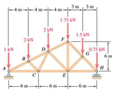
The force in each of the member of the double-pitch roof truss using method of joints and whether each member is in tension or compression.
Answer to Problem 6.165RP
The force in member
Explanation of Solution
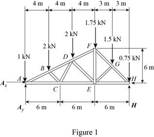
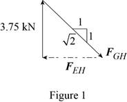
The free-body diagram of the truss is shown in figure 1.
The sum of the moments about the point
Here,
Write the equation for
Here,
Put the above equation in equation (I).
The
Here,
Write the expression for
Here,
Put the above equation in equation (II).
The
Here,
Write the expression for
Put the above equation in equation (III).
Here,
Substitute
The free-body diagram of joint A is shown in figure 2.
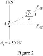
The joint A is subject to the forces exerted by
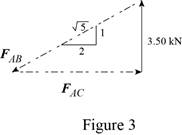
Obtain the magnitudes of the two forces from proportion.
Here,
The free-body diagram of the joint B is shown in figure 4.
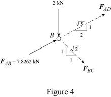
Write the equilibrium equations.
Here,
Write the expression for
Here,
Put the above equation in equation (IV).
The
Here,
Write the expression for
Put the above equation in equation (VI).
Multiply equation (V) by
Subtract equation (VII) from (V).
The free-body diagram of the joint C is shown in figure 5.
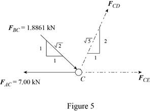
Write the expression for
Here,
Put the above equation in equation (VI).
Write the expression for
Here,
Put the above equation in equation (IV).
The free-body diagram of the joint D is shown in figure 6.
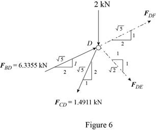
Write the expression for
Here,
Put the above equation in equation (IV).
Write the expression for
Put the above equation in equation (VI).
Add equations (VIII) and (IX).
Subtract equation (IX) from equation (VIII).
Consider the joint F. The free-body diagram of the joint F is shown in figure 7.
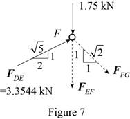
Write the expression for
Here,
Put the above equation in equation (IV).
Write the expression for
Here,
Put the above equation in equation (VI).
Consider the joint G. The free-body diagram of the joint G is shown in figure 8.
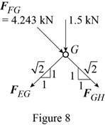
Write the expression for
Here,
Put the above equation in equation (IV).
Write the expression for
Put the above equation in equation (VI).
Add equations (X) and (XI).
Subtract equation (X) from equation (XI).
Consider the joint H. The free-body diagram of the joint H is shown in figure 9.
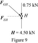
The joint H is subject to the forces exerted by
Obtain the magnitudes of the force from proportion.
Conclusion:
Thus, the force in member
Want to see more full solutions like this?
Chapter 6 Solutions
VECTOR MECH...,STAT.+DYNA.(LL)-W/ACCESS


- The primary material used in the production of glass products is silica sand. True or Falsearrow_forwardWhich one of the following is the most common polymer type in fiber-reinforced polymer composites? thermosets thermoplastics elastomers none of the abovearrow_forwardA pattern for a product is larger than the actual finished part. True or Falsearrow_forward
- Two forces are applied as shown to a hook support. The magnitude of P is 38 N. 50 N 25° DG a 터 Using trigonometry, determine the required angle a such that the resultant R of the two forces applied to the support will be horizontal. The value of a isarrow_forwardNo chatgpt pls will upvotearrow_forward101 the three shafts if the diameter ratio is 2 (D/d = 2)? Ans. na, tension = 1.21, na, bending = 1.19, na, torsion = 1.17. 6.32 A material with a yield strength of S₁ = 350 MPa is subjected to the stress state shown in Sketch c. What is the factor of safety based on the maximum shear stress and distortion energy theories? Ans. For MSST, n, = 11.67. 50 MPa 85 MPa 20 MPa 70 MPa Sketch c, for Problems 6.32 and 6.33arrow_forward
- Can you draw the left view of the first orthographic projectionarrow_forwardImportant: I've posted this question twice and received incorrect answers. I've clearly stated that I don't require AI-generated working out. I need a genuine, expert-written solution with proper working. If you can't provide that, refer this question to someone who can please!. Note: Please provide a clear, step-by-step handwritten solution (no AI involvement). I require an expert-level answer and will assess it based on quality and accuracy with that I'll give it a thumbs up or down!. Hence, refer to the provided image for clarity. Double-check everything for correctness before submitting. Thank you!arrow_forwardNote: Please provide a clear, step-by-step simplified handwritten working out (no explanations!), ensuring it is done without any AI involvement. I require an expert-level answer, and I will assess and rate based on the quality and accuracy of your work and refer to the provided image for more clarity. Make sure to double-check everything for correctness before submitting appreciate your time and effort!. Question:arrow_forward
 Elements Of ElectromagneticsMechanical EngineeringISBN:9780190698614Author:Sadiku, Matthew N. O.Publisher:Oxford University Press
 Mechanics of Materials (10th Edition)Mechanical EngineeringISBN:9780134319650Author:Russell C. HibbelerPublisher:PEARSON
 Thermodynamics: An Engineering ApproachMechanical EngineeringISBN:9781259822674Author:Yunus A. Cengel Dr., Michael A. BolesPublisher:McGraw-Hill Education
 Control Systems EngineeringMechanical EngineeringISBN:9781118170519Author:Norman S. NisePublisher:WILEY
 Mechanics of Materials (MindTap Course List)Mechanical EngineeringISBN:9781337093347Author:Barry J. Goodno, James M. GerePublisher:Cengage Learning
 Engineering Mechanics: StaticsMechanical EngineeringISBN:9781118807330Author:James L. Meriam, L. G. Kraige, J. N. BoltonPublisher:WILEY