Vector Mechanics for Engineers: Statics and Dynamics
11th Edition
ISBN: 9780073398242
Author: Ferdinand P. Beer, E. Russell Johnston Jr., David Mazurek, Phillip J. Cornwell, Brian Self
Publisher: McGraw-Hill Education
bartleby

Videos

Textbook Question
Book Icon
Chapter 6.3, Problem 6.120P

6.119 through 6.121 Each of the frames shown consists of two L-shaped members connected by two rigid links. For each frame, determine the reactions at the supports and indicate whether the frame is rigid.
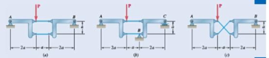
Chapter 6.3, Problem 6.120P, 6.119 through 6.121 Each of the frames shown consists of two L-shaped members connected by two rigid

Fig. P6.120

Expert Solution & Answer
Check Mark
To determine

The reactions at the frame and the rigidness of the frame.

Answer to Problem 6.120P

The reactions at the frame for figure (a) is B=2.06P_ at 14.04°_ above the negative x axis, A=2.06P_ at 14.04°_ above the positive x axis and the rigidness of the frame in figure (a) rigid, for figure (b) the reaction is P=0 and the system is not rigid, and for figure (c) the reactions are B=1.031P_ at 14.04°_ above the positive x axis, A=1.250P_ at 36.9°_ above the negative x axis and the system is rigid.

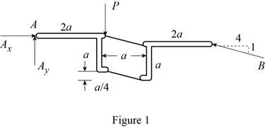
Explanation of Solution

The following figure gives the free body diagram of the member in figure P6.120(a).

Vector Mechanics for Engineers: Statics and Dynamics, Chapter 6.3, Problem 6.120P , additional homework tip  1

Write the equation to find the moment of force.

M=Fa

Here, F is the force acting and a is the perpendicular distance from the force to the point about which the moment is calculated.

Write the equation to find the total moment about the point A.

ΣMA=Σ(Fa)

Write the equations for equilibrium for the free body diagram in figure 1.

ΣMA=0 (I)

ΣFy=0 (II)

ΣFx=0 (III)

Here, MA is the torque about the point A, Fx is the force in the x direction, and Fy is the force in the y direction.

The following figure gives the free body diagram of the member in figure P6.120(b).

Vector Mechanics for Engineers: Statics and Dynamics, Chapter 6.3, Problem 6.120P , additional homework tip  2

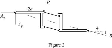
Write the equations for equilibrium for the free body diagram in figure 2.

ΣMA=0 (IV)

Here, MA is the torque about the point A.

The following figure gives the free body diagram of the member in figure P6.120(c).

Vector Mechanics for Engineers: Statics and Dynamics, Chapter 6.3, Problem 6.120P , additional homework tip  3

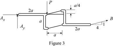
Write the equations for equilibrium for the free body diagram in figure 3.

ΣMA=0 (V)

ΣFy=0 (VI)

ΣFx=0 (VII)

Here, MA is the torque about the point A, Fx is the force in the x direction, and Fy is the force in the y direction.

Write the expression to find the magnitude of the vector from its components.

C=Cx2+Cy2 (VIII)

Here,Cx is the x component of the vector C and Cy is the y component of the vector C.

Write the equation to find the angle of orientation of the vector C.

θ=tan1(CyCx) (IX)

Conclusion:

Solve equation (I) using figure 1.

2aPa4417B+5a117B=0

Rewrite the above equation to find B.

B=2.06P

Solve equation (II) using figure 1.

Ax417B=0

Substitute 2.06P for B in the above equation and rearrange it to find Ax.

Ax=417(2.06P)=1.99P=2P

Solve equation (III) using figure 1.

Ay117B=0

Substitute 2.06P for B and rewrite the above equation to find Ay.

Ay=117(2.06P)=P2

Rewrite equation (VIII) in terms of the vector A.

A=Ax2+Ay2

Substitute 2P for Ax, and P2 for Ay in the above equation.

A=(2P)2+(P2)2=2.061P

Rewrite equation (IX) in terms of the vector A.

θ=tan1(AyAx)

Substitute 2P for Ax, and P2 for Ay in the above equation.

θ=tan1(P22P)=14.036°=14.04°

Solve equation (IV) using figure 2.

2aP=0P=0

Solve equation (V) using figure 3.

5a117B+3a4417B2aP=0

Rewrite the above equation to find B.

B=174P=1.0307P

Solve equation (VI) using figure 3.

Ax+417B=0

Substitute 17P4 for B in the above equation and rearrange it to find Ax.

Ax=417(17P4)=P

Solve equation (VII) using figure 3.

AyP+117B=0

Substitute 17P4 for B and rewrite the above equation to find Ay.

Ay=PP4=3P4

Rewrite equation (VIII) in terms of the vector A.

A=Ax2+Ay2

Substitute P for Ax, and 3P4 for Ay in the above equation.

A=(P)2+(3P4)2=1.250P

Rewrite equation (IX) in terms of the vector A.

θ=tan1(AyAx)

Substitute P for Ax, and 3P4 for Ay in the above equation.

θ=tan1(3P4P)=36.86°

Therefore, the reactions at the frame for figure (a) is B=2.06P_ at 14.04°_ above the negative x axis, A=2.06P_ at 14.04°_ above the positive x axis and the rigidness of the frame in figure (a) rigid, for figure (b) the reaction is P=0 and the system is not rigid, and for figure (c) the reactions are B=1.031P_ at 14.04°_ above the positive x axis, A=1.250P_ at 36.9°_ above the negative x axis and the system is rigid.

Want to see more full solutions like this?

Subscribe now to access step-by-step solutions to millions of textbook problems written by subject matter experts!
Students have asked these similar questions
a problem existed at the stocking stations of a mini-load AS/RS (automated storage and retrieval system) of a leading electronics manufacturer (Fig.1). At these stations, operators fill the bin delivered by the crane with material arriving in a tote over a roller conveyor. The conveyor was designed at such a height that it was impossible to reach the hooks comfortably even with the tote extended. Furthermore, cost consideration came into the picture and the conveyor height was not reduced. Instead, a step stool was considered to enable the stocker to reach the moving hooks comfortably. The height of the hooks from the floor is 280.2 cm (AD). The tote length is 54.9 cm. The projection of tote length and arm reach, CB = 66.1 cm. a) What anthropometric design principles would you follow to respectively calculate height, length, and width of the step to make it usable to a large number of people? b) What is the minimum height (EF) of the step with no shoe allowance? c) What is the minimum…
Qu. 5 Composite materials are becoming more widely used in aircraft industry due to their high strength, low weight and excellent corrosion resistant properties. As an engineer who is given task to design the I beam section of an aircraft (see Figure 7) please, answer the following questions given the material properties in Table 3. Determine the Moduli of Elasticity of Carbon/Epoxy, Aramid/Epoxy, and Boron /Epoxy composites in the longitudinal direction, given that the composites consist of 25 vol% epoxy and 75 vol% fiber. What are the specific moduli of each of these composites? What are the specific strengths (i.e. specific UTS) of each of these composites? What is the final cost of each of these composites?please show all work step by step problems make sure to see formula material science
Mueh Battery operated train Coll 160,000kg 0.0005 0.15 5m² 1.2kg/m³ CD Af Pair 19 пре neng 0.98 0.9 0.88 Tesla Prated Tesla Trated "wheel ng Joxle 270 kW 440NM 0,45m 20 8.5kg m2 the middle Consider a drive cycle of a 500km trip with 3 stops in Other than the acceleration and deceleration associated with the three stops, the tran maintains constat cruise speed velocity of 324 km/hr. The tran will fast charge at each stop for 15 min at a rate Peharge = 350 kW ΟΙ 15MIN Stop w charging (350kW) (ผม τ (AN GMIJ t 6M 1) HOW MUCH DISTANCE dace is covered DURING THE ACCELERATION TO 324 km/hr? 2) DETERMINE HOW LONG (IN seconds) the tran will BE TRAVELING AT FULL SPEED 2 ? 3) CALCULATE THE NET ENERGY GAW PER STOP ete

Chapter 6 Solutions

Vector Mechanics for Engineers: Statics and Dynamics

Ch. 6.1 - Determine the force in each member of the Gambrel...Ch. 6.1 - Determine the force in each member of the Howe...Ch. 6.1 - Using the method of joints, determine the force in...Ch. 6.1 - 6.14 Determine the force in each member of the...Ch. 6.1 - Determine the force in each member of the Warren...Ch. 6.1 - Solve Problem 6.15 assuming that the load applied...Ch. 6.1 - Determine the force in each member of the Pratt...Ch. 6.1 - The truss shown is one of several supporting an...Ch. 6.1 - Determine the force in each member of the Pratt...Ch. 6.1 - Prob. 6.20PCh. 6.1 - Determine the force in each of the members located...Ch. 6.1 - Determine the force in member DE and in each of...Ch. 6.1 - Determine the force in each of the members located...Ch. 6.1 - The portion of truss shown represents the upper...Ch. 6.1 - For the tower and loading of Prob. 6.24 and...Ch. 6.1 - Solve Problem 6.24 assuming that the cables...Ch. 6.1 - Determine the force in each member of the truss...Ch. 6.1 - Determine the force in each member of the truss...Ch. 6.1 - 6.29 Determine whether the trusses of Probs....Ch. 6.1 - 6.30 Determine whether the trusses of Probs....Ch. 6.1 - Prob. 6.31PCh. 6.1 - Prob. 6.32PCh. 6.1 - For the given loading, determine the zero-force...Ch. 6.1 - Prob. 6.34PCh. 6.1 - Prob. 6.35PCh. 6.1 - Prob. 6.36PCh. 6.1 - The truss shown consists of six members and is...Ch. 6.1 - The truss shown consists of nine members and is...Ch. 6.1 - The truss shown consists of nine members and is...Ch. 6.1 - Solve Prob. 6.39 for P = 0 and Q = (900 N)k. 6.39...Ch. 6.1 - The truss shown consists of 18 members and is...Ch. 6.1 - The truss shown consists of 18 members and is...Ch. 6.2 - 6.43 A Mansard roof truss is loaded as shown....Ch. 6.2 - 6.44 A Mansard roof truss is loaded as shown....Ch. 6.2 - Determine the force in members BD and CD of the...Ch. 6.2 - Determine the force in members DF and DG of the...Ch. 6.2 - Prob. 6.47PCh. 6.2 - Prob. 6.48PCh. 6.2 - Determine the force in members CD and DF of the...Ch. 6.2 - Determine the force in members CE and EF of the...Ch. 6.2 - Determine the force in members DE and DF of the...Ch. 6.2 - Prob. 6.52PCh. 6.2 - Determine the force in members DF and DE of the...Ch. 6.2 - Prob. 6.54PCh. 6.2 - Prob. 6.55PCh. 6.2 - 6.56 A monosloped roof truss is loaded as shown....Ch. 6.2 - A Howe scissors roof truss is loaded as shown....Ch. 6.2 - A Howe scissors roof truss is loaded as shown....Ch. 6.2 - Determine the force in members AD, CD, and CE of...Ch. 6.2 - Determine the force in members DG, FG, and FH of...Ch. 6.2 - 6.61 Determine the force in members DG and FI of...Ch. 6.2 - Prob. 6.62PCh. 6.2 - Prob. 6.63PCh. 6.2 - Prob. 6.64PCh. 6.2 - The diagonal members in the center panels of the...Ch. 6.2 - The diagonal members in the center panels of the...Ch. 6.2 - Prob. 6.67PCh. 6.2 - Prob. 6.68PCh. 6.2 - Classify each of the structures shown as...Ch. 6.2 - Classify each of the structures shown as...Ch. 6.2 - Prob. 6.71PCh. 6.2 - 6.70 through 6.74 classify as determinate or...Ch. 6.2 - 6.70 through 6.74 classify as determinate or...Ch. 6.2 - 6.70 through 6.74 classify as determinate or...Ch. 6.3 - For the frame and loading shown, draw the...Ch. 6.3 - For the frame and loading shown, draw the...Ch. 6.3 - Draw the free-body diagram(s) needed to determine...Ch. 6.3 - Knowing that the pulley has a radius of 0.5 m,...Ch. 6.3 - 6.75 and 6.76 Determine the force in member BD and...Ch. 6.3 - 6.75 and 6.76 Determine the force in member BD and...Ch. 6.3 - For the frame and loading shown, determine the...Ch. 6.3 - Determine the components of all forces acting on...Ch. 6.3 - Prob. 6.79PCh. 6.3 - Prob. 6.80PCh. 6.3 - Determine the components of all forces acting on...Ch. 6.3 - Determine the components of all forces acting on...Ch. 6.3 - Determine the components of the reactions at A and...Ch. 6.3 - Determine the components of the reactions at D and...Ch. 6.3 - Determine the components of the reactions at A and...Ch. 6.3 - Determine the components of the reactions at A and...Ch. 6.3 - 6.87 Determine the components of the reactions at...Ch. 6.3 - The 48-lb load can be moved along the line of...Ch. 6.3 - The 48-lb load is removed and a 288-lb in....Ch. 6.3 - (a) Show that, when a frame supports a pulley at...Ch. 6.3 - Knowing that each pulley has a radius of 250 mm,...Ch. 6.3 - Knowing that the pulley has a radius of 75 mm,...Ch. 6.3 - Prob. 6.93PCh. 6.3 - Prob. 6.94PCh. 6.3 - Prob. 6.95PCh. 6.3 - Prob. 6.96PCh. 6.3 - Prob. 6.97PCh. 6.3 - Prob. 6.98PCh. 6.3 - Knowing that P = 90 lb and Q = 60 lb, determine...Ch. 6.3 - Knowing that P = 90 lb and Q = 60 lb, determine...Ch. 6.3 - For the frame and loading shown, determine the...Ch. 6.3 - For the frame and loading shown, determine the...Ch. 6.3 - Prob. 6.103PCh. 6.3 - 6.104 Solve Prob. 6.103 assuming that the 360-lb...Ch. 6.3 - For the frame and loading shown, determine the...Ch. 6.3 - Prob. 6.106PCh. 6.3 - The axis of the three-hinge arch ABC is a parabola...Ch. 6.3 - The axis of the three-hinge arch ABC is a parabola...Ch. 6.3 - Prob. 6.109PCh. 6.3 - Prob. 6.110PCh. 6.3 - 6.111, 6.112, and 6.113 Members ABC and CDE are...Ch. 6.3 - Prob. 6.112PCh. 6.3 - 6.111, 6.112, and 6.113 Members ABC and CDE are...Ch. 6.3 - Prob. 6.114PCh. 6.3 - Solve Prob. 6.112 assuming that the force P is...Ch. 6.3 - Prob. 6.116PCh. 6.3 - Prob. 6.117PCh. 6.3 - Prob. 6.118PCh. 6.3 - 6.119 through 6.121 Each of the frames shown...Ch. 6.3 - 6.119 through 6.121 Each of the frames shown...Ch. 6.3 - 6.119 through 6.121 Each of the frames shown...Ch. 6.4 - An 84-lb force is applied to the toggle vise at C....Ch. 6.4 - For the system and loading shown, draw the...Ch. 6.4 - Prob. 6.7FBPCh. 6.4 - The position of member ABC is controlled by the...Ch. 6.4 - The shear shown is used to cut and trim...Ch. 6.4 - A 100-lb force directed vertically downward is...Ch. 6.4 - Prob. 6.124PCh. 6.4 - The control rod CE passes through a horizontal...Ch. 6.4 - Solve Prob. 6.125 when (a) = 0, (b) = 6. Fig....Ch. 6.4 - The press shown is used to emboss a small seal at...Ch. 6.4 - The press shown is used to emboss a small seal at...Ch. 6.4 - Prob. 6.129PCh. 6.4 - The pin at B is attached to member ABC and can...Ch. 6.4 - Arm ABC is connected by pins to a collar at B and...Ch. 6.4 - Arm ABC is connected by pins to a collar at B and...Ch. 6.4 - The Whitworth mechanism shown is used to produce a...Ch. 6.4 - Prob. 6.134PCh. 6.4 - Prob. 6.135PCh. 6.4 - Prob. 6.136PCh. 6.4 - 6.137 and 6.138 Rod CD is attached to the collar D...Ch. 6.4 - 6.137 and 6.138 Rod CD is attached to the collar D...Ch. 6.4 - Two hydraulic cylinders control the position of...Ch. 6.4 - Prob. 6.140PCh. 6.4 - Prob. 6.141PCh. 6.4 - Prob. 6.142PCh. 6.4 - Prob. 6.143PCh. 6.4 - Prob. 6.144PCh. 6.4 - The pliers shown are used to grip a...Ch. 6.4 - 6.146 Determine the magnitude of the gripping...Ch. 6.4 - In using the bolt cutter shown, a worker applies...Ch. 6.4 - Prob. 6.148PCh. 6.4 - Prob. 6.149PCh. 6.4 - and 6.150 Determine the force P that must be...Ch. 6.4 - Prob. 6.151PCh. 6.4 - Prob. 6.152PCh. 6.4 - 6.153 The motion of the bucket of the front-end...Ch. 6.4 - Prob. 6.154PCh. 6.4 - The telescoping arm ABC is used to provide an...Ch. 6.4 - The telescoping arm ABC of Prob. 6.155 can be...Ch. 6.4 - The motion of the backhoe bucket shown is...Ch. 6.4 - Prob. 6.158PCh. 6.4 - Prob. 6.159PCh. 6.4 - In the planetary gear system shown, the radius of...Ch. 6.4 - Two shafts AC and CF, which lie in the vertical xy...Ch. 6.4 - Two shafts AC and CF, which lie in the vertical xy...Ch. 6.4 - The large mechanical tongs shown are used to grab...Ch. 6 - Using the method of joints, determine the force in...Ch. 6 - Using the method of joints, determine the force in...Ch. 6 - A stadium roof truss is loaded as shown. Determine...Ch. 6 - A stadium roof truss is loaded as shown. Determine...Ch. 6 - Determine the components of all forces acting on...Ch. 6 - Prob. 6.169RPCh. 6 - Knowing that the pulley has a radius of 50 mm,...Ch. 6 - For the frame and loading shown, determine the...Ch. 6 - For the frame and loading shown, determine the...Ch. 6 - Water pressure in the supply system exerts a...Ch. 6 - A couple M with a magnitude of 1.5 kNm is applied...Ch. 6 - Prob. 6.175RP
Knowledge Booster
Background pattern image
Mechanical Engineering
Learn more about
Need a deep-dive on the concept behind this application? Look no further. Learn more about this topic, mechanical-engineering and related others by exploring similar questions and additional content below.
Similar questions
SEE MORE QUESTIONS
Recommended textbooks for you
Text book image
Elements Of Electromagnetics
Mechanical Engineering
ISBN:9780190698614
Author:Sadiku, Matthew N. O.
Publisher:Oxford University Press
Text book image
Mechanics of Materials (10th Edition)
Mechanical Engineering
ISBN:9780134319650
Author:Russell C. Hibbeler
Publisher:PEARSON
Text book image
Thermodynamics: An Engineering Approach
Mechanical Engineering
ISBN:9781259822674
Author:Yunus A. Cengel Dr., Michael A. Boles
Publisher:McGraw-Hill Education
Text book image
Control Systems Engineering
Mechanical Engineering
ISBN:9781118170519
Author:Norman S. Nise
Publisher:WILEY
Text book image
Mechanics of Materials (MindTap Course List)
Mechanical Engineering
ISBN:9781337093347
Author:Barry J. Goodno, James M. Gere
Publisher:Cengage Learning
Text book image
Engineering Mechanics: Statics
Mechanical Engineering
ISBN:9781118807330
Author:James L. Meriam, L. G. Kraige, J. N. Bolton
Publisher:WILEY
Material Science, Phase Diagrams, Part 1; Author: Welt der Werkstoffe;https://www.youtube.com/watch?v=G83ZaoB3XCc;License: Standard Youtube License