
Videos
The force exerted by each cylinder shown in figure
Answer to Problem 6.158P
The force exerted by the cylinder
Explanation of Solution
Take all
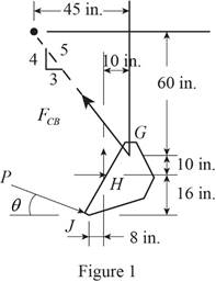
Let P is the force exerted on the bucket at J.
The magnitude of force
The free body diagram of the bucket is sketched below as figure 1.
Here,
Write the expression for the moment at
Here,
Above equation implies that net moment at any point is the sum of product of each force acting on the system and perpendicular distance of the force and the point.
The moment at
Thus, the complete expression of net anticlockwise moment
Here,
At equilibrium, the sum of the moment acting at
Write the expression for the total moment acting at
From figure 1 , write the expression for the
From figure 1 , write the expression for the
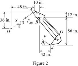
The free body diagram of the bucket and arm
Here,
Write the expression for the moment at
Here,
Above equation implies that net moment at any point is the sum of product of each force acting on the system and perpendicular distance of the force and the point.
The moment at
Thus, the complete expression of net anticlockwise moment
Here,
At equilibrium, the sum of the moment acting at
Write the expression for the total moment acting at
From figure 2 , write the expression for the
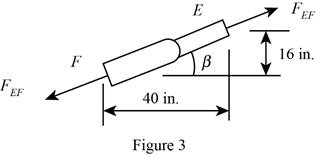
Geometry of cylinder
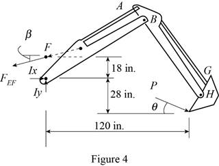
The free body diagram of the bucket and both arms is sketched below as figure 4.
Here,
Write the expression for the moment at
Here,
Above equation implies that net moment at any point is the sum of product of each force acting on the system and perpendicular distance of the force and the point.
The moment at
Thus, the complete expression of net anticlockwise moment
Here,
At equilibrium, the sum of the moment acting at
Write the expression for the total moment acting at
From figure 3 , write the expression for the
Calculation:
Substitute
The negative sign indicate that the cylinder undergoes compression.
Substitute
The negative sign indicate that the cylinder undergoes compression.
Rearrange the equation (X) to get

Substitute
The positive sign indicate that the cylinder
Therefore, the force exerted by the cylinder
Want to see more full solutions like this?
Chapter 6 Solutions
Vector Mechanics for Engineers: Statics and Dynamics


- Drawing the section view for the following multiview drawing AutoCAD you see the section pratice I need to show how to autocadarrow_forwardA boiler with 80% efficiency produces steam at 40bar and 500 C at a rate of 1.128kg/s. The temperature of the feed water is raised from 25 C to 125 C in the economizer and the ambient air is drawn to the boiler at a rate of 2.70 kg/s at 16 C. The flue gases leave the chimney at rate of 3 kg/s at 150 C with specific heat of 1.01 kJ/kg.K. The dryness fraction of steam collected in the steam drum is 0.95. 1- Determine the heat value of the fuel. 2- The equivalence evaporation. 3- Draw the heat balance sheet.arrow_forwardA rotating shaft is made of 42 mm by 4 mm thick cold-drawn round steel tubing and has a 6 mm diameter hole drilled transversely through it. The shaft is subjected to a pulsating torque fluctuating from 20 to 160 Nm and a completely reversed bending moment of 200 Nm. The steel tubing has a minimum strength of Sut = 410 MPa (60 ksi). The static stress-concentration factor for the hole is 2.4 for bending and 1.9 for torsion. The maximum operating temperature is 400˚C and a reliability of 99.9% is to be assumed. Find the factor of safety for infinite life using the modified Goodman failure criterion.arrow_forward
- I need help with a MATLAB code. This code just keeps running and does not give me any plots. I even reduced the tolerance from 1e-9 to 1e-6. Can you help me fix this? Please make sure your solution runs. % Initial Conditions rev = 0:0.001:2; g1 = deg2rad(1); g2 = deg2rad(3); g3 = deg2rad(6); g4 = deg2rad(30); g0 = deg2rad(0); Z0 = 0; w0 = [0; Z0*cos(g0); -Z0*sin(g0)]; Z1 = 5; w1 = [0; Z1*cos(g1); -Z1*sin(g1)]; Z2 = 11; w2 = [0; Z2*cos(g2); -Z2*sin(g2)]; [v3, psi3, eta3] = Nut_angle(Z2, g2, w2); plot(v3, psi3) function dwedt = K_DDE(~, w_en) % Extracting the initial condtions to a variable % Extracting the initial condtions to a variable w = w_en(1:3); e = w_en(4:7); Z = w_en(8); I = 0.060214; J = 0.015707; x = (J/I) - 1; y = Z - 1; s = Z; % Kinematic Differential Equations dedt = zeros(4,1); dedt(1) = pi*(e(3)*(s-w(2)-1) + e(2)*w(3) + e(4)*w(1)); dedt(2) = pi*(e(4)*(w(2)-1-s) + e(3)*w(1) - e(1)*w(3)); dedt(3) = pi*(-e(1)*(s-w(2)-1) - e(2)*w(1) + e(4)*w(3));…arrow_forwardalpha 1 is not zero alpha 1 can equal alpha 2 use velocity triangle to solve for alpha 1 USE MATLAB ONLY provide typed code solve for velocity triangle and dont provide copied answer Turbomachienery . GIven: vx = 185 m/s, flow angle = 60 degrees, (leaving a stator in axial flow) R = 0.5, U = 150 m/s, b2 = -a3, a2 = -b3 Find: velocity triangle , a. magnitude of abs vel leaving rotor (m/s) b. flow absolute angles (a1, a2, a3) 3. flow rel angles (b2, b3) d. specific work done e. use code to draw vel. diagram Use this code for plot % plots Velocity Tri. in Ch4 function plotveltri(al1,al2,al3,b2,b3) S1L = [0 1]; V1x = [0 0]; V1s = [0 1*tand(al3)]; S2L = [2 3]; V2x = [0 0]; V2s = [0 1*tand(al2)]; W2s = [0 1*tand(b2)]; U2x = [3 3]; U2y = [1*tand(b2) 1*tand(al2)]; S3L = [4 5]; V3x = [0 0]; V3r = [0 1*tand(al3)]; W3r = [0 1*tand(b3)]; U3x = [5 5]; U3y = [1*tand(b3) 1*tand(al3)]; plot(S1L,V1x,'k',S1L,V1s,'r',... S2L,V2x,'k',S2L,V2s,'r',S2L,W2s,'b',U2x,U2y,'g',...…arrow_forward3. Find a basis of eigenvectors and diagonalize. 4 0 -19 7 a. b. 1-42 16 12-20 [21-61arrow_forward
- 2. Find the eigenvalues. Find the corresponding eigenvectors. 6 2 -21 [0 -3 1 3 31 a. 2 5 0 b. 3 0 -6 C. 1 1 0 -2 0 7 L6 6 0 1 1 2. (Hint: λ = = 3)arrow_forwardUSE MATLAB ONLY provide typed code solve for velocity triangle and dont provide copied answer Turbomachienery . GIven: vx = 185 m/s, flow angle = 60 degrees, (leaving a stator in axial flow) R = 0.5, U = 150 m/s, b2 = -a3, a2 = -b3 Find: velocity triangle , a. magnitude of abs vel leaving rotor (m/s) b. flow absolute angles (a1, a2, a3) 3. flow rel angles (b2, b3) d. specific work done e. use code to draw vel. diagram Use this code for plot % plots Velocity Tri. in Ch4 function plotveltri(al1,al2,al3,b2,b3) S1L = [0 1]; V1x = [0 0]; V1s = [0 1*tand(al3)]; S2L = [2 3]; V2x = [0 0]; V2s = [0 1*tand(al2)]; W2s = [0 1*tand(b2)]; U2x = [3 3]; U2y = [1*tand(b2) 1*tand(al2)]; S3L = [4 5]; V3x = [0 0]; V3r = [0 1*tand(al3)]; W3r = [0 1*tand(b3)]; U3x = [5 5]; U3y = [1*tand(b3) 1*tand(al3)]; plot(S1L,V1x,'k',S1L,V1s,'r',... S2L,V2x,'k',S2L,V2s,'r',S2L,W2s,'b',U2x,U2y,'g',... S3L,V3x,'k',S3L,V3r,'r',S3L,W3r,'b',U3x,U3y,'g',...... 'LineWidth',2,'MarkerSize',10),...…arrow_forwardUSE MATLAB ONLY provide typed code solve for velocity triangle and dont provide copied answer Turbomachienery . GIven: vx = 185 m/s, flow angle = 60 degrees, R = 0.5, U = 150 m/s, b2 = -a3, a2 = -b3 Find: velocity triangle , a. magnitude of abs vel leaving rotor (m/s) b. flow absolute angles (a1, a2, a3) 3. flow rel angles (b2, b3) d. specific work done e. use code to draw vel. diagram Use this code for plot % plots Velocity Tri. in Ch4 function plotveltri(al1,al2,al3,b2,b3) S1L = [0 1]; V1x = [0 0]; V1s = [0 1*tand(al3)]; S2L = [2 3]; V2x = [0 0]; V2s = [0 1*tand(al2)]; W2s = [0 1*tand(b2)]; U2x = [3 3]; U2y = [1*tand(b2) 1*tand(al2)]; S3L = [4 5]; V3x = [0 0]; V3r = [0 1*tand(al3)]; W3r = [0 1*tand(b3)]; U3x = [5 5]; U3y = [1*tand(b3) 1*tand(al3)]; plot(S1L,V1x,'k',S1L,V1s,'r',... S2L,V2x,'k',S2L,V2s,'r',S2L,W2s,'b',U2x,U2y,'g',... S3L,V3x,'k',S3L,V3r,'r',S3L,W3r,'b',U3x,U3y,'g',...... 'LineWidth',2,'MarkerSize',10),... axis([-1 6 -4 4]), ...…arrow_forward
- The answer should equal to 1157. Please sent me the solution. Thank you!arrow_forwardBONUS: If the volume of the 8cm x 6.5cm x 6cm Block of Aluminum was 312cm3 before machining, find how much material was removed when the fixture below was machined. +2 2.00 cm 6.00 cm 2.50 cm 6.50 cm 1.00 cm 2.50 cm 11.00 cm 8.00 cm 30 CP 9411 FL.4) (m² 1157 Area of triangle = 1/2*B*H Area of circle = лR² Circumference of a circle = 2πR 6.00 cm 6.50 cm 1.50 cm Radius 1.50 cm 1.00 cmarrow_forwardConsider a 5m by 5m wet concret patio with an average water film thickness of .2mm. Now wind at 50 km/h is blowing over the surface. If the air is at 1 atm, 15oC and 35 percent relative humidity, determine how long it will take for the patio to completely dry.arrow_forward
 Elements Of ElectromagneticsMechanical EngineeringISBN:9780190698614Author:Sadiku, Matthew N. O.Publisher:Oxford University Press
 Mechanics of Materials (10th Edition)Mechanical EngineeringISBN:9780134319650Author:Russell C. HibbelerPublisher:PEARSON
 Thermodynamics: An Engineering ApproachMechanical EngineeringISBN:9781259822674Author:Yunus A. Cengel Dr., Michael A. BolesPublisher:McGraw-Hill Education
 Control Systems EngineeringMechanical EngineeringISBN:9781118170519Author:Norman S. NisePublisher:WILEY
 Mechanics of Materials (MindTap Course List)Mechanical EngineeringISBN:9781337093347Author:Barry J. Goodno, James M. GerePublisher:Cengage Learning
 Engineering Mechanics: StaticsMechanical EngineeringISBN:9781118807330Author:James L. Meriam, L. G. Kraige, J. N. BoltonPublisher:WILEY