
Concept explainers
Videos
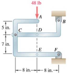
The 48-lb load is removed and a 288-lb · in. clockwise couple is applied successively at A, D, and E. Determine the components of the reactions at Band F if the couple is applied (a) at A, (b) at D, (c) at E.
(a)
The component of reactions at point B and F when the couple is applied at A.
Answer to Problem 6.89P
The x component of the reaction force at point B is
The x component of force applied is
Explanation of Solution
The free body diagram of the problem 6.89P is shown in figure 1 below.
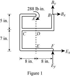
A clockwise couple is applied at A,D, and E. Due to this couple, resultant reaction forces are experienced in points A, D, and E.
First consider the couple applied at point A.
Write the equation to find the sum of moments of force at point F.
Here,
Since the sum of moments of force at a point of a system in equilibrium is zero, rewrite the equation for the sum of moments.
Write the equation to find the x components of force.
Here,
Since the sum of forces at a point is zero in equilibrium, the above equation is rewritten.
Substitute
Write the equation to find the sum of y component of forces.
Here,
No force is applied in the y direction, therefore there will be no reaction also.
Consider figure 2.
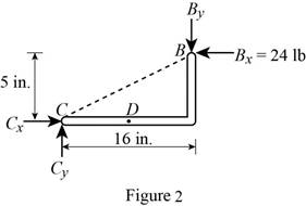
Write the equation to find the y component of reaction force at point B.
Here,
Rewrite equation (I) to find the value of
Conclusion:
Observe figure 2.
Substitute
The y component of reaction force at point B is having a magnitude of
Substitute
The y component of the force applied at point b is
Therefore, the x component of the reaction force at point B is
The x component of force applied is
(b)
The component of reactions at point B and F when the couple is applied at D.
Answer to Problem 6.89P
The x component of the reaction force at point B is
The x component of force applied is
Explanation of Solution
The free body diagram of the problem 6.89P is shown in figure 1.
A clockwise couple is applied at A,D, and E. Due to this couple, resultant reaction forces are experienced in points A, D, and E.
Consider the couple applied at point D.
Write the equation to find the sum of moments of force at point F.
Here,
Since the sum of moments of force at a point of a system in equilibrium is zero, rewrite the equation for the sum of moments.
Write the equation to find the x components of force.
Here,
Since the sum of forces at a point is zero in equilibrium, the above equation is rewritten.
Substitute
Write the equation to find the sum of y component of forces.
Here,
No force is applied in the y direction, therefore there will be no reaction also.
Consider figure 3.
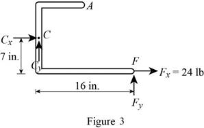
Write the equation to find the y component of reaction force at point B.
Here,
Rewrite equation (I) to find the value of
Conclusion:
Observe figure 3.
Substitute
The y component of force at point B is having a magnitude of
Substitute
The y component of the reaction force applied at point B is
Therefore, the x component of the reaction force at point B is
The x component of force applied is
(c)
The component of reactions at point B and F when the couple is applied at E.
Answer to Problem 6.89P
The x component of the reaction force at point B is
The x component of force applied is
Explanation of Solution
The free body diagram of the problem 6.89P is shown in figure 1.
A clockwise couple is applied at A,D, and E. Due to this couple, resultant reaction forces are experienced in points A, D, and E.
First consider the couple applied at point E.
Write the equation to find the sum of moments of force at point F.
Here,
Since the sum of moments of force at a point of a system in equilibrium is zero, rewrite the equation for the sum of moments.
Write the equation to find the x components of force.
Here,
Since the sum of forces at a point is zero in equilibrium, the above equation is rewritten.
Substitute
Write the equation to find the sum of y component of forces.
Here,
No force is applied in the y direction, therefore there will be no reaction also.
Consider figure 4.
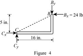
Write the equation to find the y component of reaction force at point B.
Here,
Rewrite equation (VII) to find the value of
Conclusion:
Observe figure 4.
Substitute
The y component of reaction force at point B is having a magnitude of
Substitute
The y component of the force applied at point b is
Therefore, the x component of the reaction force at point B is
The x component of force applied is
Want to see more full solutions like this?
Chapter 6 Solutions
Vector Mechanics for Engineers: Statics and Dynamics


- (I) [40 Points] Using centered finite difference approximations as done in class, solve the equation for O: d20 dx² + 0.010+ Q=0 subject to the boundary conditions shown in the stencil below. Do this for two values of Q: (a) Q = 0.3, and (b) Q= √(0.5 + 2x)e-sinx (cos(5x)+x-0.5√1.006-x| + e −43*|1+.001+x* | * sin (1.5 − x) + (cosx+0.001 + ex-1250+ sin (1-0.9x)|) * x - 4.68x4. For Case (a) (that is, Q = 0.3), use the stencil in Fig. 1. For Case (b), calculate with both the stencils in Fig. 1 and Fig 2. For all the three cases, show a table as well as a plot of O versus x. Discuss your results. Use MATLAB and hand in the MATLAB codes. 1 0=0 x=0 2 3 4 0=1 x=1 Fig 1 1 2 3 4 5 6 7 8 9 10 11 0=0 x=0 0=1 x=1 Fig 2arrow_forwardFig 2 (II) [60 Points] Using centered finite difference approximation as done in class, solve the equation: 020 020 + მx2 მy2 +0.0150+Q=0 subject to the boundary conditions shown in the stencils below. Do this for two values of Q: (a) Q = 0.3, and (b) Q = 10.5x² + 1.26 * 1.5 x 0.002 0.008. For Case (a) (that is, Q = 0.3) use Fig 3. For Case (b), use both Fig. 3 and Fig 4. For all the three cases, show a table as well as the contour plots of versus (x, y), and the (x, y) heat flux values at all the nodes on the boundaries x = 1 and y = 1. Discuss your results. Use MATLAB and hand in the MATLAB codes. (Note that the domain is (x, y)e[0,1] x [0,1].) 0=0 0=0 4 8 12 16 10 Ꮎ0 15 25 9 14 19 24 3 11 15 0=0 8-0 0=0 3 8 13 18 23 2 6 сл 5 0=0 10 14 6 12 17 22 1 6 11 16 21 13 e=0 Fig 3 Fig 4 Textbook: Numerical Methods for Engineers, Steven C. Chapra and Raymond P. Canale, McGraw-Hill, Eighth Edition (2021).arrow_forwardShip construction question. Sketch and describe the forward arrangements of a ship. Include componets of the structure and a explanation of each part/ term. Ive attached a general fore end arrangement. Simplfy construction and give a brief describion of the terms.arrow_forward
- Problem 1 Consider R has a functional relationship with variables in the form R = K xq xx using show that n ✓ - (OR 1.) = i=1 2 Их Ux2 Ихэ 2 (177)² = ² (1)² + b² (12)² + c² (1)² 2 UR R x2 x3arrow_forward4. Figure 3 shows a crank loaded by a force F = 1000 N and Mx = 40 Nm. a. Draw a free-body diagram of arm 2 showing the values of all forces, moments, and torques that act due to force F. Label the directions of the coordinate axes on this diagram. b. Draw a free-body diagram of arm 2 showing the values of all forces, moments, and torques that act due to moment Mr. Label the directions of the coordinate axes on this diagram. Draw a free body diagram of the wall plane showing all the forces, torques, and moments acting there. d. Locate a stress element on the top surface of the shaft at A and calculate all the stress components that act upon this element. e. Determine the principal stresses and maximum shear stresses at this point at A.arrow_forward3. Given a heat treated 6061 aluminum, solid, elliptical column with 200 mm length, 200 N concentric load, and a safety factor of 1.2, design a suitable column if its boundary conditions are fixed-free and the ratio of major to minor axis is 2.5:1. (Use AISC recommended values and round the ellipse dimensions so that both axes are whole millimeters in the correct 2.5:1 ratio.)arrow_forward
- 1. A simply supported shaft is shown in Figure 1 with w₁ = 25 N/cm and M = 20 N cm. Use singularity functions to determine the reactions at the supports. Assume El = 1000 kN cm². Wo M 0 10 20 30 40 50 60 70 80 90 100 110 cm Figure 1 - Problem 1arrow_forwardPlease AnswerSteam enters a nozzle at 400°C and 800 kPa with a velocity of 10 m/s and leaves at 375°C and 400 kPa while losing heat at a rate of 26.5 kW. For an inlet area of 800 cm2, determine the velocity and the volume flow rate of the steam at the nozzle exit. Use steam tables. The velocity of the steam at the nozzle exit is m/s. The volume flow rate of the steam at the nozzle exit is m3/s.arrow_forward2. A support hook was formed from a rectangular bar. Find the stresses at the inner and outer surfaces at sections just above and just below O-B. -210 mm 120 mm 160 mm 400 N B thickness 8 mm = Figure 2 - Problem 2arrow_forward
 International Edition---engineering Mechanics: St...Mechanical EngineeringISBN:9781305501607Author:Andrew Pytel And Jaan KiusalaasPublisher:CENGAGE L