
Fundamentals of Electric Circuits
6th Edition
ISBN: 9780078028229
Author: Charles K Alexander, Matthew Sadiku
Publisher: McGraw-Hill Education
expand_more
expand_more
format_list_bulleted
Concept explainers
Videos
Textbook Question
Chapter 6.2, Problem 5PP
Under dc conditions, find the energy stored in the capacitors in Fig. 6.13.
Answer: 20.25 mJ, 3.375 mJ.
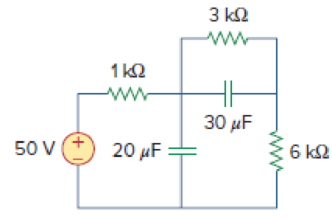
Figure 6.13
For Practice Prob. 6.5.
Expert Solution & Answer
Want to see the full answer?
Check out a sample textbook solution
Students have asked these similar questions
Fill in the chart and answer questions
Answer problems 10, 11, and 12 using the following information:An addition is being planned to a school building. You have been asked to determine theload that will be added to the panelboard that will serve this addition.The addition will be a building 80 ft 3 50 ft. It will consist of four classrooms, every40 ft 3 20 ft and a corridor that is 10-ft wide
The following loads will be installed:Each classroom:12 fluorescent luminaires, 2 ft 3 4 ft @ 85 VA each20 duplex receptaclesAC unit, 208-volt, 1-phase @ 5000 VACorridor:5 fluorescent luminaires, 1 ft 3 8 ft @ 85 VA each8 duplex receptaclesExterior:4 wall-mounted luminaires @ 125 VA each4 duplex receptacles
10. The calculated load is__________ VA.11. The connected load is__________ VA.12. The neutral load is_____________ VA.
A 1200-ampere service was installed, consisting of three sets of 600 kcmil THHN/THWN copper conductors per phase. The electrical contractor was careful to cut theconductors the same length. When the utility crew made up the connections at theservice heads, they cut the conductors to different lengths to make their connectionssimpler. The actual lengths of the service-entrance conductors in a given phase ended up being20 ft (6.1 m), 22 ft (6.7 m), and 24 ft (7.3 m). The maximum ampacity of a 600-kcmilTHHN/THWN copper conductor is 420 amperes using the 75°C column of Table310.16. This is more than adequate for the calculated 1200 amperes when three conductors are run in parallel. Determine how the load of 1200 amperes would divide in each of the three paralleledconductors in a phase.
Determine the conductor sizes for a feeder to a panelboard. It is a 120/240-volt,single-phase system. The OCPD has a rating of 100 amperes. The calculated load is15,600 VA. All the loads are 120 volts.
Chapter 6 Solutions
Fundamentals of Electric Circuits
Ch. 6.2 - What is the voltage across a 4.5-F capacitor if...Ch. 6.2 - If a 10-F capacitor is connected to a voltage...Ch. 6.2 - The current through a 100-F capacitor is i(t) = 50...Ch. 6.2 - Figure 6.11 For Practice Prob. 6.4. An initially...Ch. 6.2 - Under dc conditions, find the energy stored in the...Ch. 6.3 - Find the equivalent capacitance seen at the...Ch. 6.3 - Find the voltage across each of the capacitors in...Ch. 6.4 - If the current through a 1-mH inductor is i(t) =...Ch. 6.4 - The terminal voltage of a 2-H inductor is v = 10(1...Ch. 6.4 - Determine vC, iL, and the energy stored in the...
Ch. 6.5 - Calculate the equivalent inductance for the...Ch. 6.5 - In the circuit of Fig. 6.34, i1(t) = 3e2t A. If...Ch. 6.6 - The integrator in Fig. 6.35(b) has R = 100 k, C =...Ch. 6.6 - The differentiator in Fig. 6.37 has R = 100 k and...Ch. 6.6 - Design an analog computer circuit to solve the...Ch. 6 - What charge is on a 5-F capacitor when it is...Ch. 6 - Capacitance is measured in: (a)coulombs (b)joules...Ch. 6 - When the total charge in a capacitor is doubled,...Ch. 6 - Can the voltage waveform in Fig. 6.42 be...Ch. 6 - The total capacitance of two 40-mF...Ch. 6 - In Fig. 6.43, if i = cos 4t and v = sin 4t, the...Ch. 6 - A 5-H inductor changes its current by 3 A in 0.2...Ch. 6 - If the current through a 10-mH inductor increases...Ch. 6 - Inductors in parallel can be combined just like...Ch. 6 - Prob. 10RQCh. 6 - If the voltage across a 7.5-F capacitor is 2te3t...Ch. 6 - A 50-F capacitor has energy w(t) = 10 cos2 377t J....Ch. 6 - Design a problem to help other students better...Ch. 6 - A voltage across a capacitor is equal to [2 2...Ch. 6 - The voltage across a 4-F capacitor is shown in...Ch. 6 - The voltage waveform in Fig. 6.46 is applied...Ch. 6 - At t = 0, the voltage across a 25-mF capacitor is...Ch. 6 - A 4-mF capacitor has the terminal voltage v=...Ch. 6 - The current through a 0.5-F capacitor is 6(1 et)...Ch. 6 - The voltage across a 5-mF capacitor is shown in...Ch. 6 - A 4-mF capacitor has the current waveform shown in...Ch. 6 - A voltage of 45e2000t V appears across a parallel...Ch. 6 - Find the voltage across the capacitors in the...Ch. 6 - Series-connected 20- and 60-pF capacitors are...Ch. 6 - Two capacitors (25 and 75 F) are connected to a...Ch. 6 - The equivalent capacitance at terminals a-b in the...Ch. 6 - Determine the equivalent capacitance for each of...Ch. 6 - Find Ceq in the circuit of Fig. 6.52 if all...Ch. 6 - Find the equivalent capacitance between terminals...Ch. 6 - Find the equivalent capacitance at terminals a-b...Ch. 6 - Determine the equivalent capacitance at terminals...Ch. 6 - Obtain the equivalent capacitance of the circuit...Ch. 6 - Using Fig. 6.57, design a problem that will help...Ch. 6 - In the circuit shown in Fig. 6.58 assume that the...Ch. 6 - (a)Show that the voltage-division rule for two...Ch. 6 - Three capacitors, C1 = 5 F, C2 = 10 F, and C3 = 20...Ch. 6 - Given that four 10-F capacitors can be connected...Ch. 6 - Obtain the equivalent capacitance of the network...Ch. 6 - Determine Ceq for each circuit in Fig. 6.61....Ch. 6 - Assuming that the capacitors are initially...Ch. 6 - If v(0) = 0, find v(t), i1(t), and i2(t) in the...Ch. 6 - In the circuit in Fig. 6.64, let is = 4.5e2t mA...Ch. 6 - Obtain the Thevenin equivalent at the terminals,...Ch. 6 - The current through a 25-mH inductor is 10et/2 A....Ch. 6 - An inductor has a linear change in current from...Ch. 6 - Design a problem to help other students better...Ch. 6 - The current through a 12-mH inductor is 4 sin 100t...Ch. 6 - The current through a 40-mH inductor is i(t)= 0,...Ch. 6 - The voltage across a 50-mH inductor is given by...Ch. 6 - The current through a 5-mH inductor is shown in...Ch. 6 - The voltage across a 2-H inductor is 20(1 e2t) V....Ch. 6 - If the voltage waveform in Fig. 6.67 is applied...Ch. 6 - The current in a 150-mH inductor increases from 0...Ch. 6 - A 100-mH inductor is connected in parallel with a...Ch. 6 - If the voltage waveform in Fig. 6.68 is applied to...Ch. 6 - Find vC, iL, and the energy stored in the...Ch. 6 - For the circuit in Fig. 6.70, calculate the value...Ch. 6 - Under steady-state dc conditions, find i and v in...Ch. 6 - Find the equivalent inductance of the circuit in...Ch. 6 - An energy-storage network consists of...Ch. 6 - Determine Leq at terminals a-b of the circuit in...Ch. 6 - Using Fig. 6.74, design a problem to help other...Ch. 6 - Find Leq at the terminals of the circuit in Fig....Ch. 6 - Find the equivalent inductance looking into the...Ch. 6 - Find Leq in each of the circuits in Fig. 6.77....Ch. 6 - Find Leq in the circuit of Fig. 6.78. Figure 6.78...Ch. 6 - Determine Leq that may be used to represent the...Ch. 6 - The current waveform in Fig. 6.80 flows through a...Ch. 6 - (a) For two inductors in series as in Fig....Ch. 6 - In the circuit of Fig. 6.82, io(0) = 2 A....Ch. 6 - Consider the circuit in Fig. 6.83. Find: (a) Leq,...Ch. 6 - Consider the circuit in Fig. 6.84. Given that v(t)...Ch. 6 - In the circuit of Fig. 6.85, sketch vo. Figure...Ch. 6 - The switch in Fig. 6.86 has been in position A for...Ch. 6 - The inductors in Fig. 6.87 are initially charged...Ch. 6 - The current i(t) through a 20-mH inductor is...Ch. 6 - An op amp integrator has R = 50 k and C = 0.04 F....Ch. 6 - A 6-V dc voltage is applied to an integrator with...Ch. 6 - An op amp integrator with R = 4 M and C = 1 F has...Ch. 6 - Using a single op amp, a capacitor, and resistors...Ch. 6 - Show how you would use a single op amp to generate...Ch. 6 - At t = 1.5 ms, calculate vo due to the cascaded...Ch. 6 - Show that the circuit in Fig. 6.90 is a...Ch. 6 - The triangular waveform in Fig. 6.91(a) is applied...Ch. 6 - An op amp differentiator has R = 250 k and C = 10...Ch. 6 - A voltage waveform has the following...Ch. 6 - The output vo of the op amp circuit in Fig....Ch. 6 - Prob. 78PCh. 6 - Figure 6.93 presents an analog computer designed...Ch. 6 - Design an analog computer to simulate the...Ch. 6 - Design an op amp circuit such that vo=10vs+2vsdt...Ch. 6 - Your laboratory has available a large number of...Ch. 6 - An 8-mH inductor is used in a fusion power...Ch. 6 - A square-wave generator produces the voltage...Ch. 6 - An electric motor can be modeled as a series...
Additional Engineering Textbook Solutions
Find more solutions based on key concepts
Why is the study of database technology important?
Database Concepts (8th Edition)
Porter’s competitive forces model: The model is used to provide a general view about the firms, the competitors...
Management Information Systems: Managing The Digital Firm (16th Edition)
What types of coolant are used in vehicles?
Automotive Technology: Principles, Diagnosis, And Service (6th Edition) (halderman Automotive Series)
The solid steel shaft AC has a diameter of 25 mm and is supported by smooth bearings at D and E. It is coupled ...
Mechanics of Materials (10th Edition)
Write a summary list of the problem-solving steps identified in the chapter, using your own words.
BASIC BIOMECHANICS
What is the importance of modeling in engineering? How are the mathematical models for engineering processes pr...
HEAT+MASS TRANSFER:FUND.+APPL.
Knowledge Booster


Learn more about
Need a deep-dive on the concept behind this application? Look no further. Learn more about this topic, electrical-engineering and related others by exploring similar questions and additional content below.Similar questions
- Calculate the neutral current in a 120/240-volt, single-phase system when the current inphase A is 20 amperes and the current in phase B is 40 amperes. The load is resistive. Calculate the neutral current in a 208Y/120-volt, 3-phase, 4-wire system when thecurrent in phase A is 0, in phase B is 40, and in phase C is 60 amperes. The load isresistivearrow_forwardCalculate the neutral current in a 208Y/120-volt, 3-phase, 4-wire system when the current in phase A is 20, in phase B is 40, and in phase C is 60 amperes. The load is resistive.arrow_forwardI need expert to solve this,if you don't know don't attempt,also show the signal flow diagramarrow_forward
- 1) A circuit is given as shown. (a) Find and label the circuit nodes. (6) Determine I, II, I₂ and V, I mm 22 +1 m 50 4 12 12v 2 ти + V ≤1652 50 mv Ми 60arrow_forwardHANDWRITTEN SOLUTION NOT USING CHATGPT PLEASEarrow_forwardDesign a full-wave rectifier power supply using a 9.52:1 transformer. Assume that the outlet is120 V rms @ 60 Hz. Further assume that the diode turn-on voltage V D(on) is 0.7 V. Pick the valueof CL such that vo has a maximum ripple of 1 V p-p . Solve for the average value of vo = Vo (notethat this may be greater than 12 V) and iD(ave) = ID.arrow_forward
arrow_back_ios
SEE MORE QUESTIONS
arrow_forward_ios
Recommended textbooks for you
 Introductory Circuit Analysis (13th Edition)Electrical EngineeringISBN:9780133923605Author:Robert L. BoylestadPublisher:PEARSON
 Delmar's Standard Textbook Of ElectricityElectrical EngineeringISBN:9781337900348Author:Stephen L. HermanPublisher:Cengage Learning
 Programmable Logic ControllersElectrical EngineeringISBN:9780073373843Author:Frank D. PetruzellaPublisher:McGraw-Hill Education
 Fundamentals of Electric CircuitsElectrical EngineeringISBN:9780078028229Author:Charles K Alexander, Matthew SadikuPublisher:McGraw-Hill Education
 Electric Circuits. (11th Edition)Electrical EngineeringISBN:9780134746968Author:James W. Nilsson, Susan RiedelPublisher:PEARSON
 Engineering ElectromagneticsElectrical EngineeringISBN:9780078028151Author:Hayt, William H. (william Hart), Jr, BUCK, John A.Publisher:Mcgraw-hill Education,
Introductory Circuit Analysis (13th Edition)
Electrical Engineering
ISBN:9780133923605
Author:Robert L. Boylestad
Publisher:PEARSON
Delmar's Standard Textbook Of Electricity
Electrical Engineering
ISBN:9781337900348
Author:Stephen L. Herman
Publisher:Cengage Learning
Programmable Logic Controllers
Electrical Engineering
ISBN:9780073373843
Author:Frank D. Petruzella
Publisher:McGraw-Hill Education
Fundamentals of Electric Circuits
Electrical Engineering
ISBN:9780078028229
Author:Charles K Alexander, Matthew Sadiku
Publisher:McGraw-Hill Education
Electric Circuits. (11th Edition)
Electrical Engineering
ISBN:9780134746968
Author:James W. Nilsson, Susan Riedel
Publisher:PEARSON
Engineering Electromagnetics
Electrical Engineering
ISBN:9780078028151
Author:Hayt, William H. (william Hart), Jr, BUCK, John A.
Publisher:Mcgraw-hill Education,
Capacitors Explained - The basics how capacitors work working principle; Author: The Engineering Mindset;https://www.youtube.com/watch?v=X4EUwTwZ110;License: Standard YouTube License, CC-BY