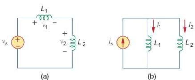
(a) For two inductors in series as in Fig. 6.81(a), show that the voltage division principle is v 1 = L 1 L 1 + L 2 v s , v 2 = L 2 L 1 + L 2 v s assuming that the initial conditions are zero. (b) For two inductors in parallel as in Fig. 6.81(b), show that the current-division principle is i 1 = L 2 L 1 + L 2 i s , i 2 = L 1 L 1 + L 2 i s assuming that the initial conditions are zero. Figure 6.81 For Prob. 6.59.
(a) For two inductors in series as in Fig. 6.81(a), show that the voltage division principle is v 1 = L 1 L 1 + L 2 v s , v 2 = L 2 L 1 + L 2 v s assuming that the initial conditions are zero. (b) For two inductors in parallel as in Fig. 6.81(b), show that the current-division principle is i 1 = L 2 L 1 + L 2 i s , i 2 = L 1 L 1 + L 2 i s assuming that the initial conditions are zero. Figure 6.81 For Prob. 6.59.
Solution Summary: The author illustrates the voltage division rule for two series inductors, wherein the current flow through each inductor is equal.
Sketch the output of the analogue computer shown below and find its closest
describing function [suppose any variable to find the DF]
+1
ew2
HI
e2
1.0 +21
LO
SJ
eo
SJ
ew
LO
1.0 +|e1|
HI
-1
ew1 ek(1 + e。)
|e1|
k =
1+|e1|
Figure V-5
Feedback Limiter Behavior
ROUNDED, DUE TO DIODE
NONLINEARITY
LIMIT VOLTAGE
409
DIODE CONDUCTS
First, write the output transaction, then draw the output wave, and then find the
Describing function. I need to solve the question step by step, with an explanation
of each step.
Sketch the output of the analogue computer shown below and find its closest
describing function [suppose any variable to find the DF]
SJ
ew2
ew₁
HI
|e2|
2
LO
1.0 +21
LO
-1
HI
Jel
1.0+|e1|
ROUNDED, DUE TO DODE
NONLINEARITY
LIMIT VOLTAGE
DIODE CONDUCTS
ew1e, -k(1+ e。)
k
=
|e1|
1+|e1|
Figure 1-5 Feedback Limiter Behavior
First, write the output transaction, then draw the output wave, and then find the
Describing function. I need to solve the question step by step, with an explanation
of each step.
Sketch the output of the analogue computer shown below and find its closest
describing function [suppose any variable to find the DF]
SJ
+1
HI
LO
e2
1.0 +21
ew2
eo
SJ
ew₁
LO
Jel
1.0 +|e1|
HI
-1
ew1 ek(1+eo)
k =
|e1|
1+|e1|
First, write the output transaction, then draw the output wave, and then find the
Describing function. I need to solve the question step by step, with an explanation
of each step.
Need a deep-dive on the concept behind this application? Look no further. Learn more about this topic, electrical-engineering and related others by exploring similar questions and additional content below.
Capacitors Explained - The basics how capacitors work working principle; Author: The Engineering Mindset;https://www.youtube.com/watch?v=X4EUwTwZ110;License: Standard YouTube License, CC-BY


 Introductory Circuit Analysis (13th Edition)Electrical EngineeringISBN:9780133923605Author:Robert L. BoylestadPublisher:PEARSON
 Delmar's Standard Textbook Of ElectricityElectrical EngineeringISBN:9781337900348Author:Stephen L. HermanPublisher:Cengage Learning
 Programmable Logic ControllersElectrical EngineeringISBN:9780073373843Author:Frank D. PetruzellaPublisher:McGraw-Hill Education
 Fundamentals of Electric CircuitsElectrical EngineeringISBN:9780078028229Author:Charles K Alexander, Matthew SadikuPublisher:McGraw-Hill Education
 Electric Circuits. (11th Edition)Electrical EngineeringISBN:9780134746968Author:James W. Nilsson, Susan RiedelPublisher:PEARSON
 Engineering ElectromagneticsElectrical EngineeringISBN:9780078028151Author:Hayt, William H. (william Hart), Jr, BUCK, John A.Publisher:Mcgraw-hill Education,